

Wire harness with exterior member
- Summary
- Abstract
- Description
- Claims
- Application Information
AI Technical Summary
Benefits of technology
Problems solved by technology
Method used
Image

Examples
embodiment 1
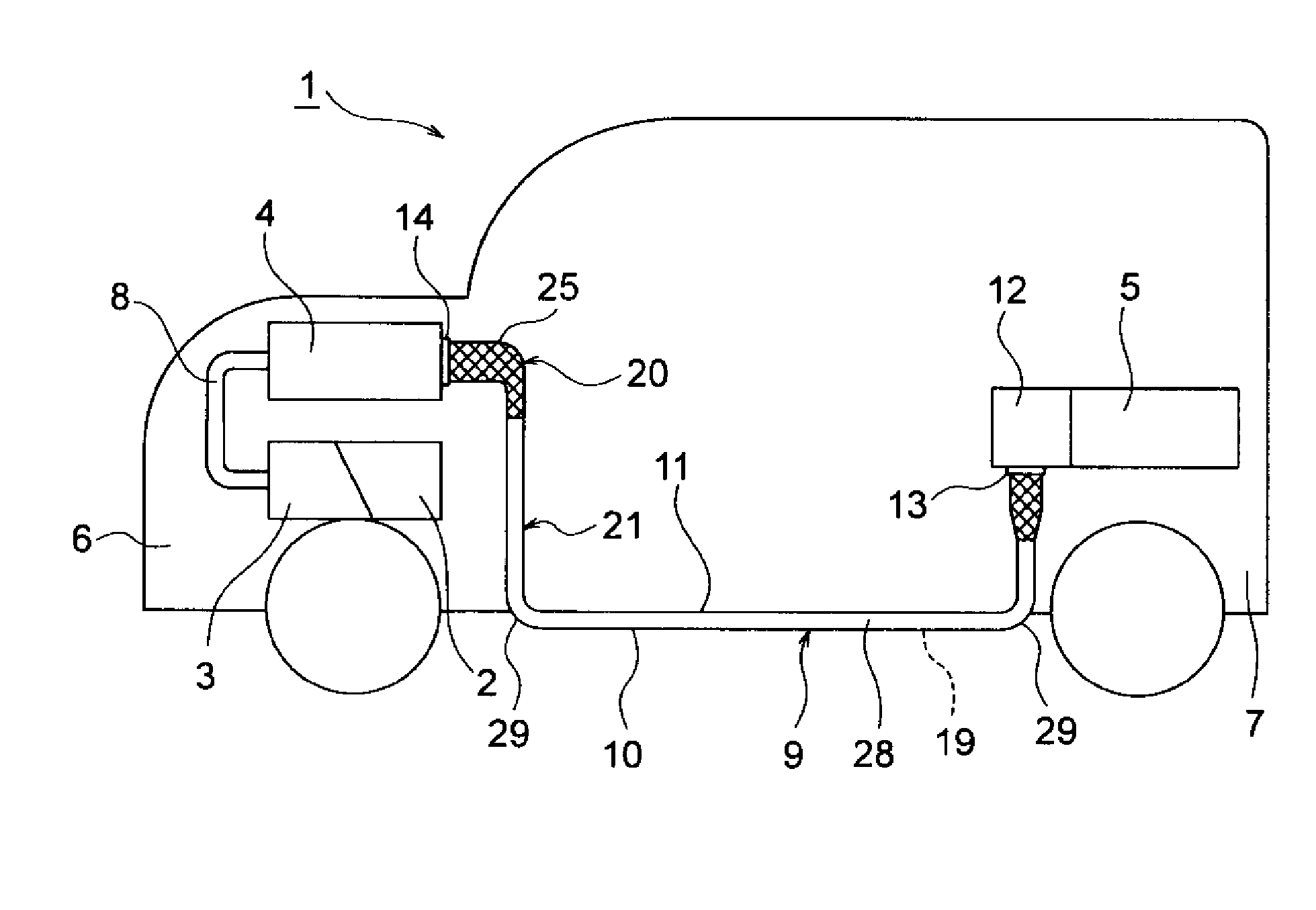
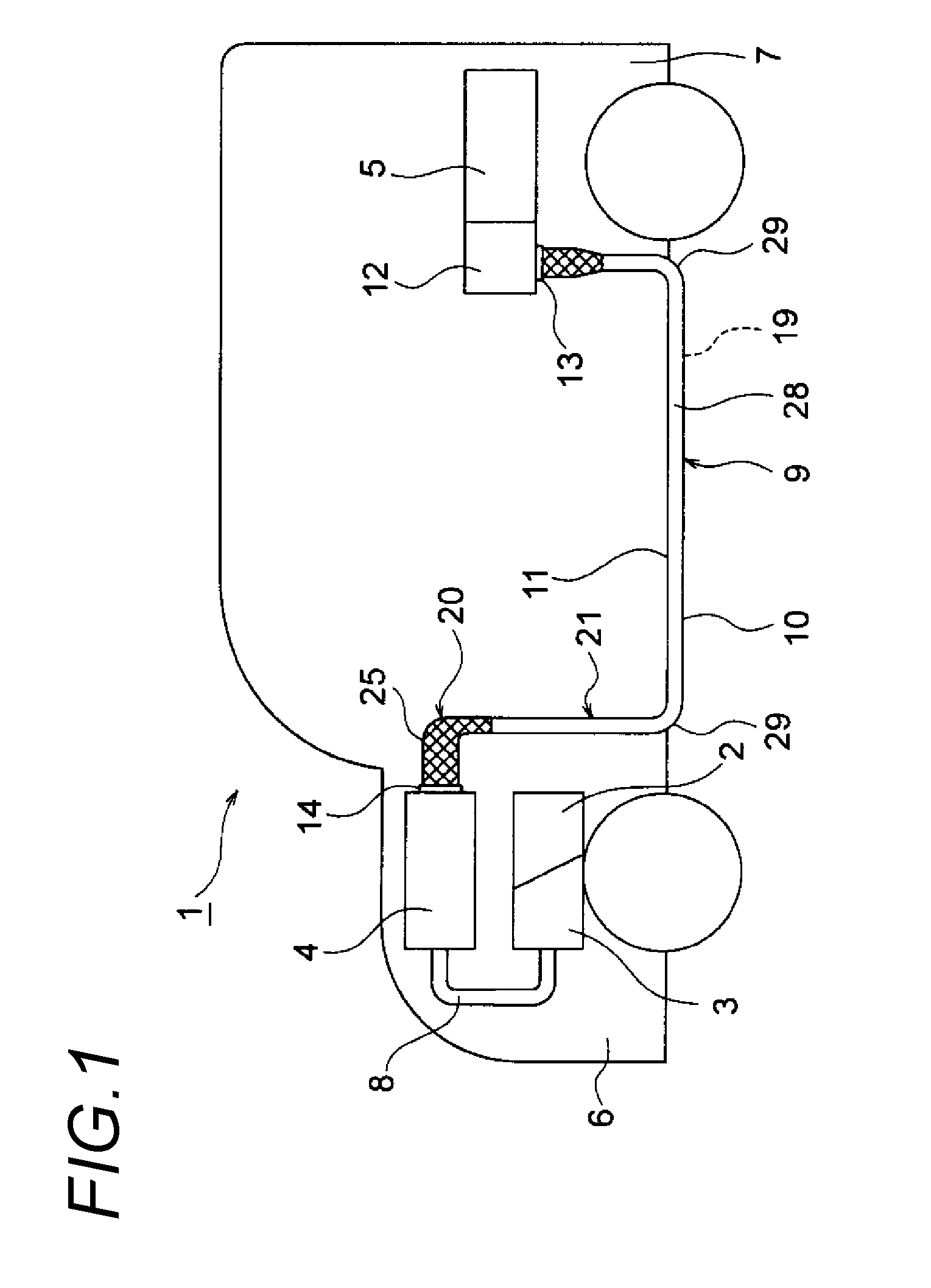
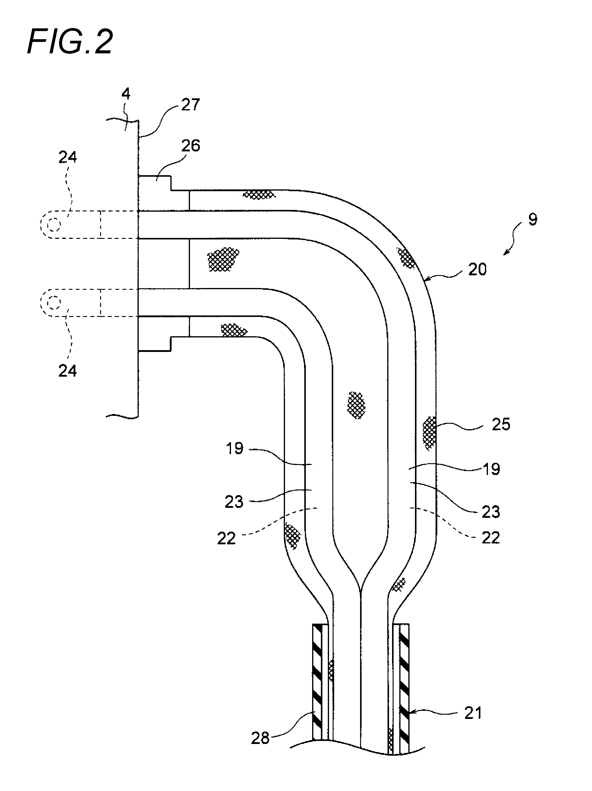
[0031]Next, an embodiment 1 is described with reference to the figures. FIG. 1 is a schematic view of a vehicle which shows an example of the wiring of a wire harness according to the embodiment 1 of the present invention. FIG. 2 is a schematic sectional view which shows one end side of the wire harness, FIG. 3 is a schematic sectional view which shows the other end side of the wire harness, and FIGS. 4A to 4C are illustrative figures related to the manufacture of the wire harness.
[0032]In the embodiment, an example in which a wire harness is applied to a hybrid vehicle (or an electric vehicle) is given and described.
[0033]In FIG. 1, a reference number 1 shows a hybrid vehicle. The hybrid vehicle 1 is a vehicle which is driven by mixing two powers of an engine 2 and a motor unit 3, and the electric power from a battery 5 (battery pack) will be supplied to the motor unit 3 via an inverter unit 4. The engine 2, the motor unit 3 and the inverter unit 4 are mounted in an engine room 6 a...
embodiment 2
[0064]Next, an embodiment 2 is described with reference to the figures. FIG. 5 is a schematic sectional view which shows another example of the wire harness according to the embodiment 2 of the present invention. The components that are identical with those in the embodiment 1 are given identical numbers, and their detailed description is omitted.
[0065]In FIG. 5, the wire harness 41 is used to electrically connect the inverter unit 4 to the battery 5, and includes two high voltage electric wires 19 (conducting paths), and a shielding member 42 which covers and shields the two high voltage electric wires 19. The shielding member 42 includes an exterior shielding member 43 (exterior member and shielding member) and terminal shielding members 44 which are provided at one end and the other end of the exterior shielding member 43.
[0066]The exterior shielding member 43 is formed of a shrinkable tube which has conductivity, that is, a conductive shrinkable tube 45, and when the conductive ...
embodiment 3
[0077]Next, an embodiment 3 is described with reference to the figures. FIG. 6 is a schematic sectional view which shows a further example of the wire harness according to the embodiment 3 of the present invention.
[0078]In FIG. 6, a wire harness 51 includes two electric wires 52 (conducting paths, herein only one electric wire is shown), an exterior shielding member 53 (exterior member and shielding member), an inverter side connecting member 54 (connecting member) which is provided at one end side of the high voltage electric wires 52, and a battery side connecting member (connecting member) which is not shown and which is provided at the other side. The battery side connecting member not shown in the figure is basically constructed like the inverter side connecting member 54.
[0079]The high voltage electric wire 52 includes a conductor 55 and an insulator 56 which covers the conductor 55. The high voltage electric wire 52 is processed so that the conductor 55 is exposed by only str...
PUM
| Property | Measurement | Unit |
|---|---|---|
| Electrical conductivity | aaaaa | aaaaa |
| Shape | aaaaa | aaaaa |
| Electrical conductor | aaaaa | aaaaa |
Abstract
Description
Claims
Application Information