Media Separation Roller Installing Mechanism, Roller Holder Unit, Media Conveyance Device, and Printer

a technology for installing mechanisms and retard rollers, which is applied in the directions of article separation, transportation and packaging, thin material processing, etc., can solve the problems of media separation force, retard rollers deteriorating, and the replacement of retard rollers is not simple, so as to achieve the effect of convenient replacemen

Inactive Publication Date: 2014-09-11
SEIKO EPSON CORP
View PDF3 Cites 7 Cited by
  • Summary
  • Abstract
  • Description
  • Claims
  • Application Information

AI Technical Summary

Benefits of technology

[0008]The present invention relates to a media separation roller installing mechanism that enables easily replacing a media separation roller, to a roller holder unit, and to a media conveyance device and a printer having the media separation roller installing mechanism.
[0009]The invention also relates to a media separation roller installing mechanism, a roller holder unit, and a unit installation part that enable easily replacing the media separation roller without requiring much space, and to a media conveyance device and a printer having the media separation roller installing mechanism.
[0010]The invention further relates to a media separation roller installing mechanism, a roller holder unit, and a unit installation part that enable easily replacing the media separation roller without the effect of pressure on the media separation roller, and to a media conveyance device and a printer having the media separation roller installing mechanism.

Problems solved by technology

The retard roller deteriorates over time, including a drop in the media separation force due to wear.
Replacing the retard roller is therefore not simple.
Replacing the retard roller is therefore not easy because the retard roller must be removed and installed while pressure is applied.

Method used


Image

  • Media Separation Roller Installing Mechanism, Roller Holder Unit, Media Conveyance Device, and Printer
  • Media Separation Roller Installing Mechanism, Roller Holder Unit, Media Conveyance Device, and Printer
  • Media Separation Roller Installing Mechanism, Roller Holder Unit, Media Conveyance Device, and Printer

Examples


Embodiment Construction

[0043]A preferred embodiment of the present invention is described below with reference to the accompanying figures. The following embodiment describes the invention applied to a printer having a reversing unit enabling two-sided (duplex) printing. The invention can obviously also be applied to printers other than printers having a reversing unit, as well as devices other than printers, including scanners and facsimile machines. The invention can also be applied to sheet media conveyance devices used in printers, and media conveyance devices that supply media to printers or other devices.

General Configuration of a Printer

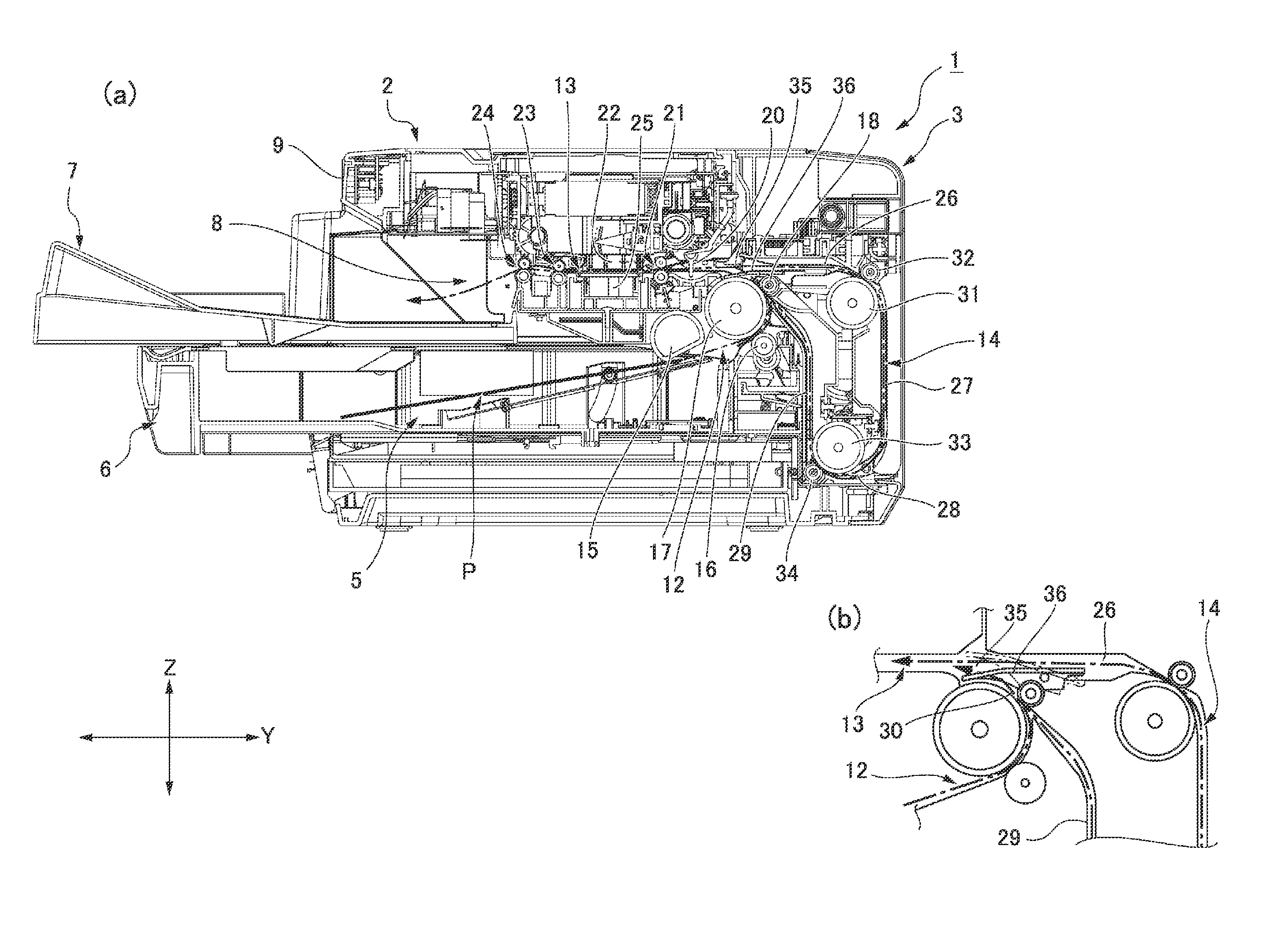
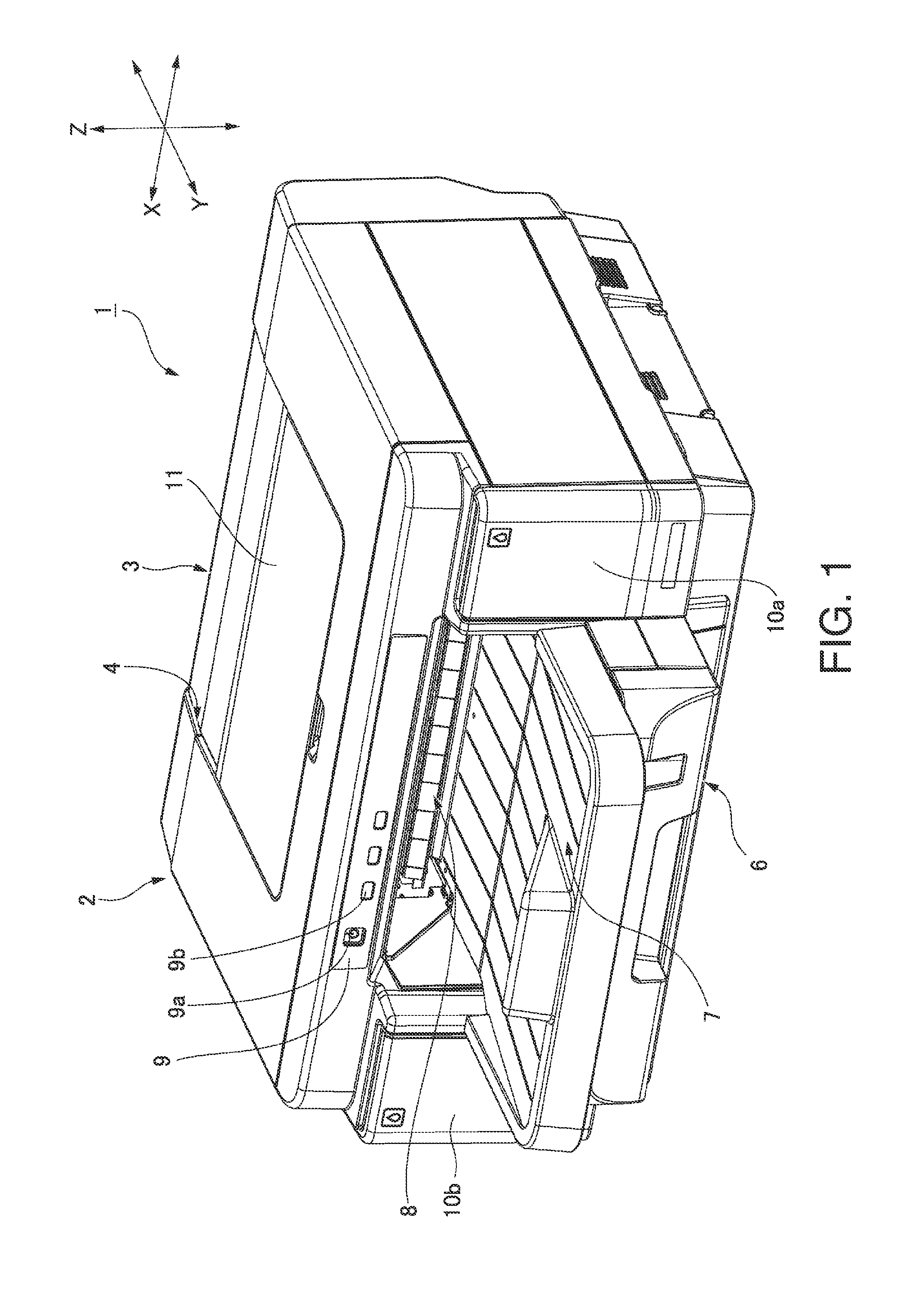
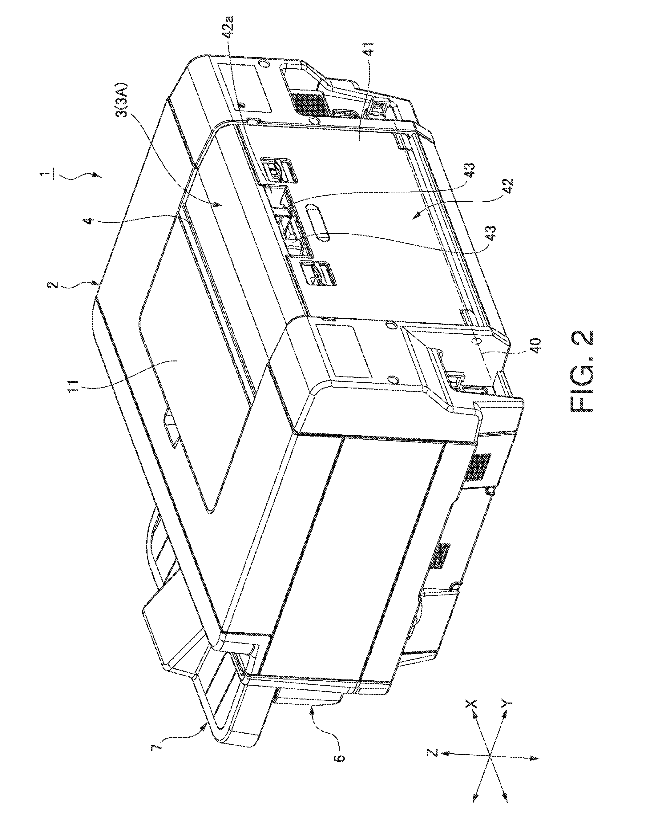
[0044]FIG. 1 is an external oblique view from the front of an inkjet printer (“printer” below) according to this embodiment of the invention, and FIG. 2 is an external oblique view of the printer from the back. FIG. 3 (a) is a vertical section view and FIG. 3 (b) is a partial section view of the internal configuration of the printer.

[0045]The general configuration o...


PUM


Abstract

A mechanism for installing a media separation roller 16 includes a roller holder unit 90 and a unit installation part 70 on the conveyance path side. The roller holder unit 90 includes a first holder 100 that supports the retard roller 16, a second holder 110 connected to the first holder 100 pivotably on an axis of holder rotation, and an urging member 130 that urges the first holder 100 to the second holder 110 around the axis of holder rotation. The retard roller 16 and tension spring 130 are removably installable to the unit installation part 70 as a unit. Replacing the retard roller 16 is therefore simple.

Description

BACKGROUND[0001]1. Technical Field[0002]The present invention relates to a media separation roller installing mechanism that installs a media separation roller for separating multifed sheet media to a position opposing a media conveyance roller. The invention also relates to a roller holder unit including the media separation roller installing mechanism. The invention further relates to a media conveyance device and a printer having the media separation roller installing mechanism.[0003]2. Related Art[0004]Devices having a media separation roller as a media separation mechanism to prevent multifeeding sheet media such as printing paper are known from the literature. The media separation roller is generally called a retard roller, and a mechanism having this roller is called a retard separation mechanism. When recording media are fed to the nipping point between the feed roller and the retard roller in this retard separation mechanism, the medium is advanced by the paper feed roller ...

Claims


Application Information

Patent Timeline
Patent Type & Authority Applications(United States)
IPC IPC(8): B65H3/06B65H5/06
CPCB65H5/06B65H3/0638B65H3/5215B65H5/062B65H5/26B65H2402/10B65H2402/31B65H2402/32B65H2402/441B65H2402/46B65H2404/144B65H2404/1521B65H2404/6111B65H2405/3322B65H2601/324B65H85/00B65H2402/54B65H2404/5511B65H2404/551B65H2404/2532
Inventor MASUBUCHI, HIROYUKIIMAE, TOSHIHIRO
Owner SEIKO EPSON CORP
Why Eureka
Try Eureka