
Resistance measuring apparatus for inspecting compression quality and measuring method using the same

a technology of resistance measurement and compression quality, which is applied in the direction of resistance/reactance/impedence, measurement devices, instruments, etc., can solve the problems of increasing the inferiority rate of final products, progressive failure and reliability failure, and affecting the quality of compression portions, so as to reduce the error of measured resistance due to measurement noise or minimize the

Inactive Publication Date: 2014-09-11
SAMSUNG DISPLAY CO LTD
View PDF21 Cites 2 Cited by
  • Summary
  • Abstract
  • Description
  • Claims
  • Application Information

AI Technical Summary

Benefits of technology

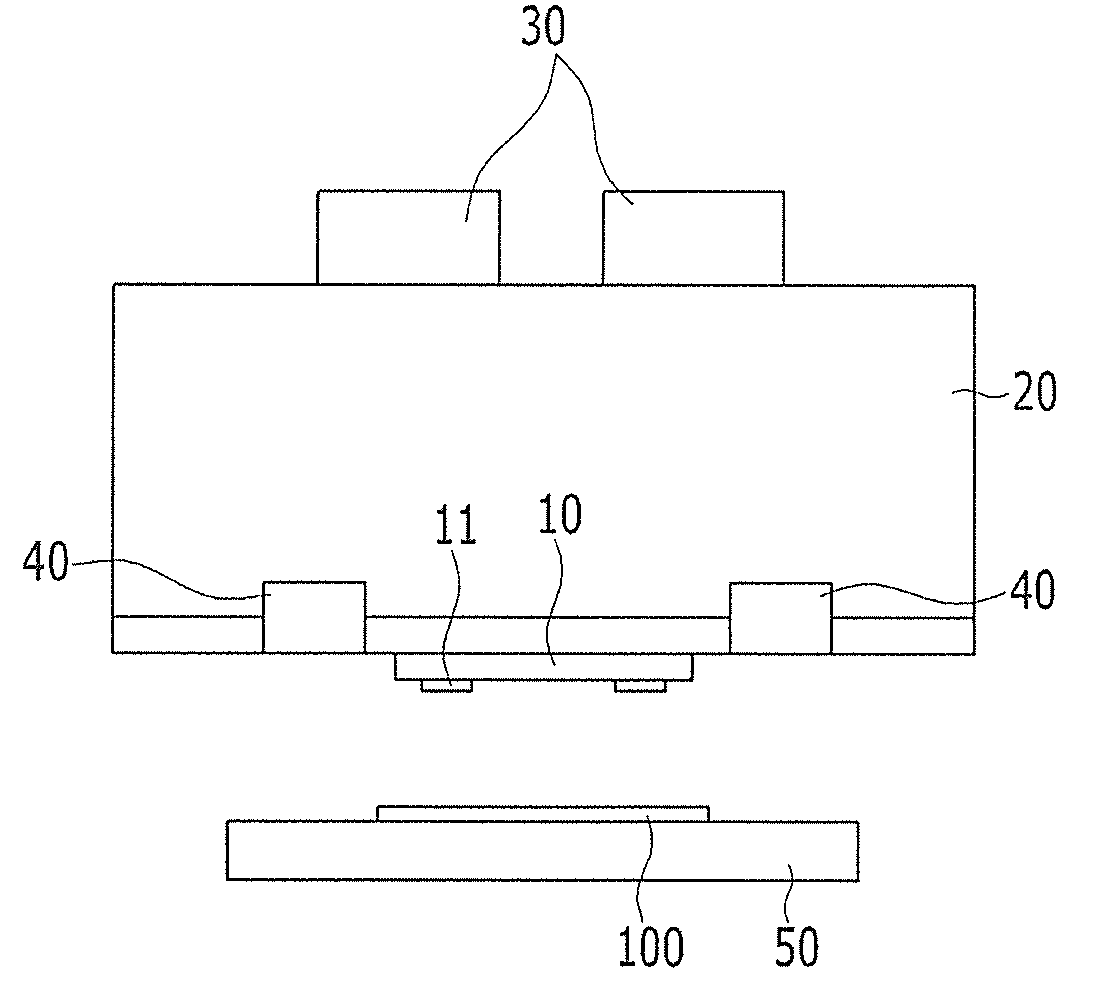
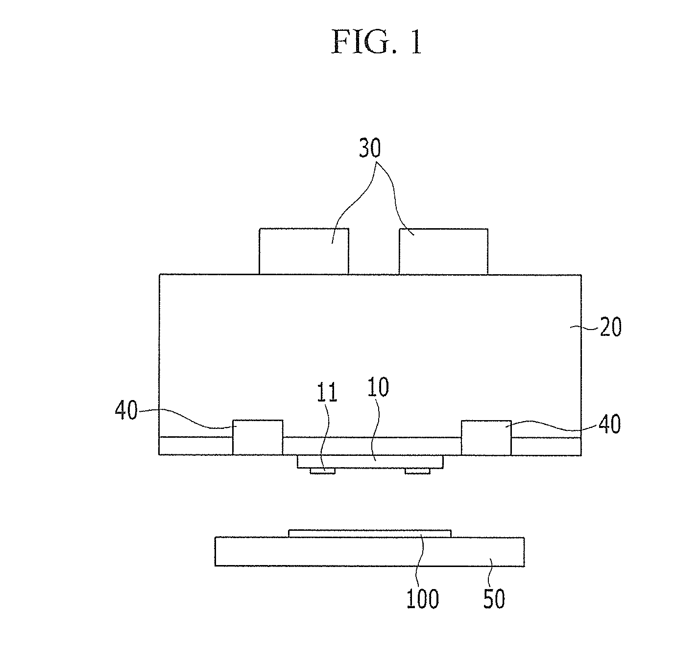
The described technology provides a resistance measuring apparatus and method for inspecting compression quality to reduce errors in measured resistance. The apparatus can control vertical pressure and smoothness of probe pins to accurately measure resistance of compression portions. It can quantify compression quality to objective data and avoid outflow errors caused by subjective determination. The inspection current is variably changed depending on resistance range to reduce measurement noise and accurately measure resistance of compression portions. The apparatus can be applied to display devices with various resistance ranges.

Problems solved by technology

However, such an inspection process using optical vision may increase an inferiority rate in final products, because failures cannot be digitalized, and the failure may cause progressive failure and reliability failure.
In addition, when a source current applied through the probe is significantly higher than a current that the compression portion can endure, the compression portion may be damaged.
When the source current is significantly lower than resistance of the compression portion, resistance of the compression portion cannot be accurately measured due to noise.
Further, not only an initial process failure, but also a potential progressive failure that cannot be detected through simple visual inspection, can be detected in advance.

Method used


Image

  • Resistance measuring apparatus for inspecting compression quality and measuring method using the same
  • Resistance measuring apparatus for inspecting compression quality and measuring method using the same
  • Resistance measuring apparatus for inspecting compression quality and measuring method using the same

Examples


Embodiment Construction

[0032]The embodiments of the present invention will be described more fully hereinafter with reference to the accompanying drawings, in which various embodiments of the invention are shown. As those skilled in the art would realize, the described embodiments may be modified in different ways, without departing from the spirit or scope of the various embodiments of the present invention.

[0033]The drawings and description are to be regarded as illustrative in nature and not restrictive. Like reference numerals designate like elements throughout the specification. In addition, the size and thickness of each component shown in the drawings may be arbitrarily shown for understanding and ease of description, but the embodiments of the present invention is not limited thereto.

[0034]It will be understood that when an element such as a layer, film, region, or substrate is referred to as being “on” another element, it can be directly on the other element, or one or more intervening elements m...


PUM


Abstract

A resistance measuring apparatus for inspecting compression quality includes a probe configured to measure resistance by contacting compression resistance measuring tags of a display device, a probe support for supporting the probe, and a torque motor coupled to the probe support and configured to control a position of the probe.

Description

CROSS-REFERENCE TO RELATED APPLICATION[0001]This application claims priority to and the benefit of Korean Patent Application No. 10-2013-0024521 filed in the Korean Intellectual Property Office on Mar. 7, 2013, the entire contents of which are incorporated herein by reference.BACKGROUND[0002]1. Field[0003]The described embodiments of the present invention relate to a resistance measuring apparatus for inspecting compression quality, and a measuring method using the same.[0004]2. Description of the Related Art[0005]In a process for a flat display device such as an organic light emitting diode (OLED) display, a liquid crystal display (LCD), and the like, a compression process is performed using an anisotropic conductive film (ACF). Such a compression process may include a film on glass (FOG) bonding process, a chip on glass (COG) bonding process, and the like.[0006]To assure stable compression quality, a compression characteristic of a compression portion (such as alignment or indenta...

Claims


Application Information

Patent Timeline
IPC IPC(8): G09G3/00
CPCG09G3/006G01R1/067G01R27/00G01R31/28
Inventor KO, YOON-DUKLEE, YONG-HEE
Owner SAMSUNG DISPLAY CO LTD
Learn More