Method and Apparatus for Multi-Axle Vehicle Alignment with Vehicle Frame Reference

a vehicle frame reference and multi-axis technology, applied in the field of machine vision vehicle wheel alignment systems, can solve the problems of vehicle fuel consumption, tire wear, and vehicle misalignment, and achieve the effect of reducing the number of vehicles that cannot be aligned correctly to the manufacturer's specifications, and reducing the number of vehicles that cannot be aligned correctly

Active Publication Date: 2014-09-11
HUNTER ENG
View PDF3 Cites 32 Cited by
  • Summary
  • Abstract
  • Description
  • Claims
  • Application Information

AI Technical Summary

Benefits of technology

[0015]It would be further advantageous to provide a vehicle alignment system capable of acquiring real-time alignment angle measurements, together with measurements of a vehicle reference axis, using a set of passive optical targets mounted to the vehicle and a set of observing cameras positioned in spaced-apart proximity to the vehicle.

Problems solved by technology

It is well known that improper alignment of the wheels of a vehicle can have adverse effects on vehicle handling, vehicle fuel consumption, and tire wear.
The problems associated with misalignment of vehicle wheels are further exacerbated on vehicles having more than two axles, such as heavy-duty trucks, busses, and trailers, which commonly include a steering axle and at least one fixed tandem axle combination.
Any vehicle alignment system which defines toe alignment relative to another axis will not be able to correctly align a vehicle to a manufacturer's specifications.
The effect of this misalignment is that the wheels on the steer axle of the vehicle must be turned to offset the “push” of the tandem axles to maintain the vehicle moving in a straight-ahead direction, resulting in tire wear on every tire of the vehicle.
This condition can be further amplified due to misalignment in the axles of towed trailers, such as in a tractor-trailer combination, resulting in rapid wear on all of the vehicle tires, increased fuel consumption, and poor vehicle handling.

Method used


Image

  • Method and Apparatus for Multi-Axle Vehicle Alignment with Vehicle Frame Reference
  • Method and Apparatus for Multi-Axle Vehicle Alignment with Vehicle Frame Reference
  • Method and Apparatus for Multi-Axle Vehicle Alignment with Vehicle Frame Reference

Examples


Embodiment Construction

[0033]The following detailed description illustrates the invention by way of example and not by way of limitation. The description enables one skilled in the art to make and use the present disclosure, and describes several embodiments, adaptations, variations, alternatives, and uses of the present disclosure, including what is presently believed to be the best mode of carrying out the present disclosure.

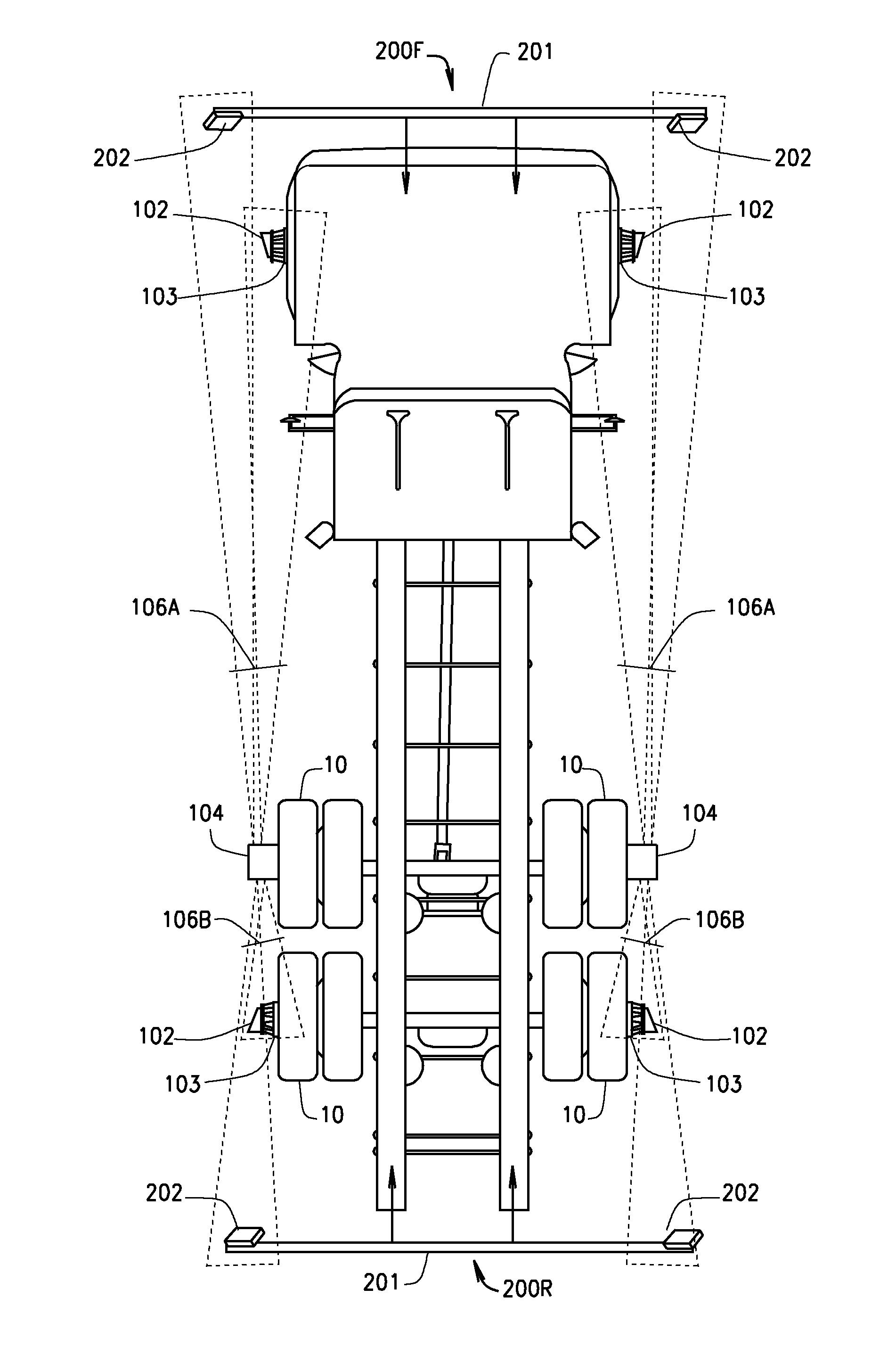
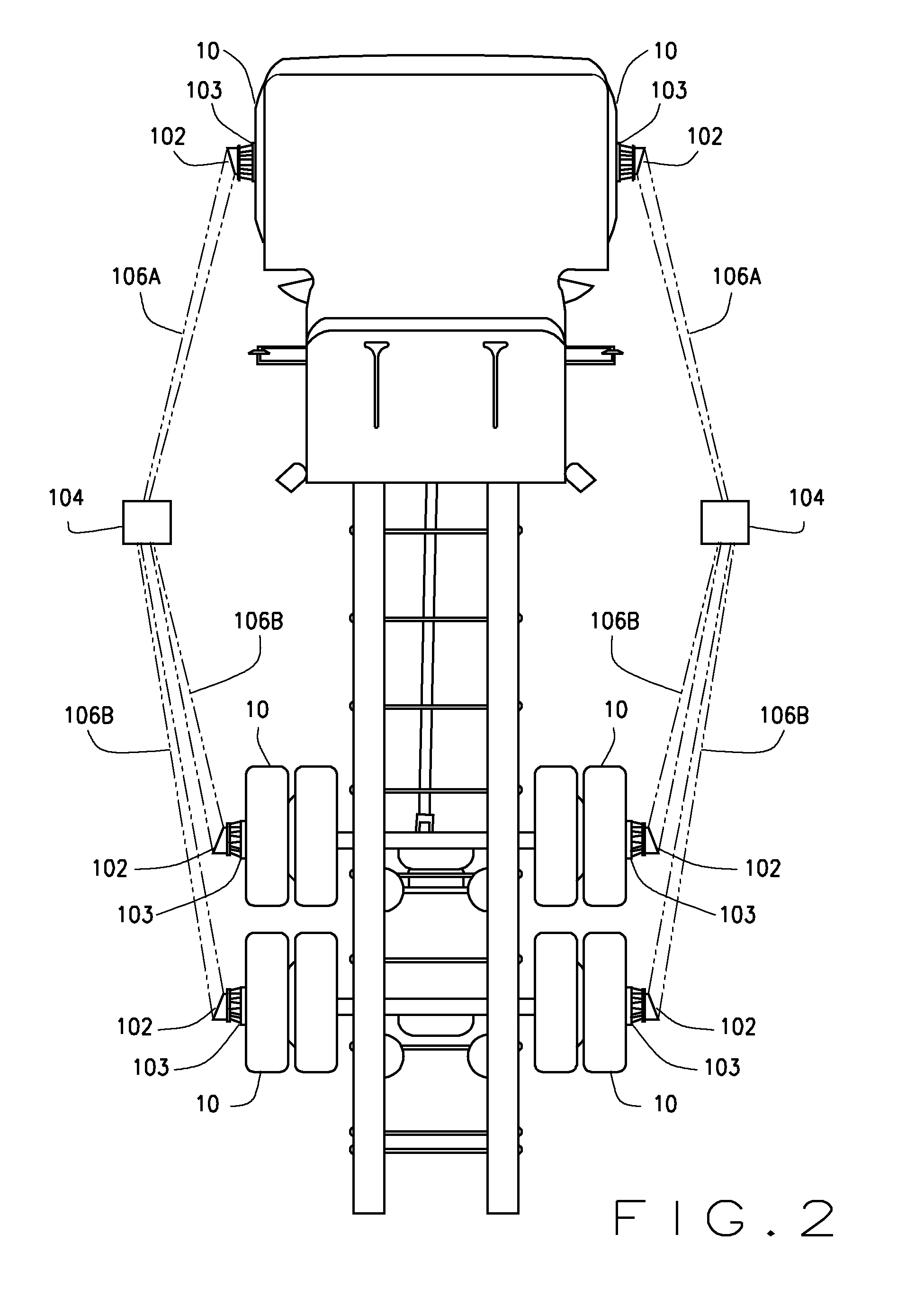
[0034]The present disclosure is described in one embodiment in the context of a machine vision vehicle wheel alignment or inspection system having optical measuring devices. The basic components and functionality of a machine vision system, including the construction of cameras or imaging sensors, optical targets, calibration procedures, image processing algorithms, and alignment angle computations are well understood in the art, and are not set forth herein. It is intended that the present disclosure may be utilized with a wide variety of machine wheel alignment or inspection syste...


PUM


Abstract

A vehicle wheel service system including a plurality of sensors positioned in proximity to a heavy-duty multi-axle vehicle, to measure angles associated with three or more axles of the vehicle without repositioning the mounting of the sensors after initiating a measurement procedure. Additional sensors, associated with a vehicle reference, such as the vehicle frame axis, are disposed to provide vehicle reference measurement data which is communicated to a processing system. The processing system is configured with software instructions to evaluate the measurement data and to determine various vehicle wheel alignment angle measurements and/or necessary vehicle adjustments for each axle relative to the vehicle reference or to a fixed axle having a determined relationship to the vehicle reference.

Description

CROSS-REFERENCE TO RELATED APPLICATIONS[0001]The present application is related to, and claims priority from, U.S. Provisional Patent Application Ser. No. 61 / 774,818 filed Mar. 8, 2013, and which is herein incorporated by reference.STATEMENT REGARDING FEDERALLY SPONSORED RESEARCH[0002]Not Applicable.BACKGROUND OF THE INVENTION[0003]The present application relates to machine vision vehicle wheel alignment systems configured to measure the alignment of the wheels of a motor vehicle, and in particular, to a machine vision vehicle wheel alignment system configured with a set of imaging sensors disposed in spaced-apart proximity to a heavy-duty motor vehicle having two or more axles in order to observe targets individually mounted to each axle of the vehicle and to the vehicle frame, to determine a set of vehicle wheel alignment angle measurements.[0004]It is well known that improper alignment of the wheels of a vehicle can have adverse effects on vehicle handling, vehicle fuel consumpti...

Claims


Application Information

Patent Timeline
Patent Type & Authority Applications(United States)
IPC IPC(8): G01B11/275
CPCG01B11/2755G01B2210/12G01B2210/143G01B2210/20G01B2210/24G01B2210/28G01B2210/30
Inventor MCCLENAHAN, JAMES W.STIEFF, MICHAEL T.BONCEK, JOHN M.STREGE, TIMOTHY A.COLARELLI, III, NICHOLAS J.
Owner HUNTER ENG
Why Eureka
Try Eureka