Perimeter pile anchor foundation

Active Publication Date: 2014-09-11
TERRACON CONSULTANTS INC
View PDF2 Cites 24 Cited by
  • Summary
  • Abstract
  • Description
  • Claims
  • Application Information

AI Technical Summary

Benefits of technology

[0017]When constructed according to either the first or the second embodiment, the ring of overlapping odd and even piles forms an arch between adjacent piles. Compression and friction between the adjacent piles resists soil caving and sloughing pressure when soil inside the generally circular perimeter of the piles is excavated.
[0018]Accordingly, one object of the present invention is to overcome the difficulties of constructing deep concrete foundations in weak soil and/or cohesionless sand which are subject to sloughing or caving in when excavated vertically by providing a perimeter pile

Problems solved by technology

Such foundations are limited by soil conditions, as weak or wet soils will cave or sluff

Method used


Image

  • Perimeter pile anchor foundation
  • Perimeter pile anchor foundation
  • Perimeter pile anchor foundation

Examples


first embodiment

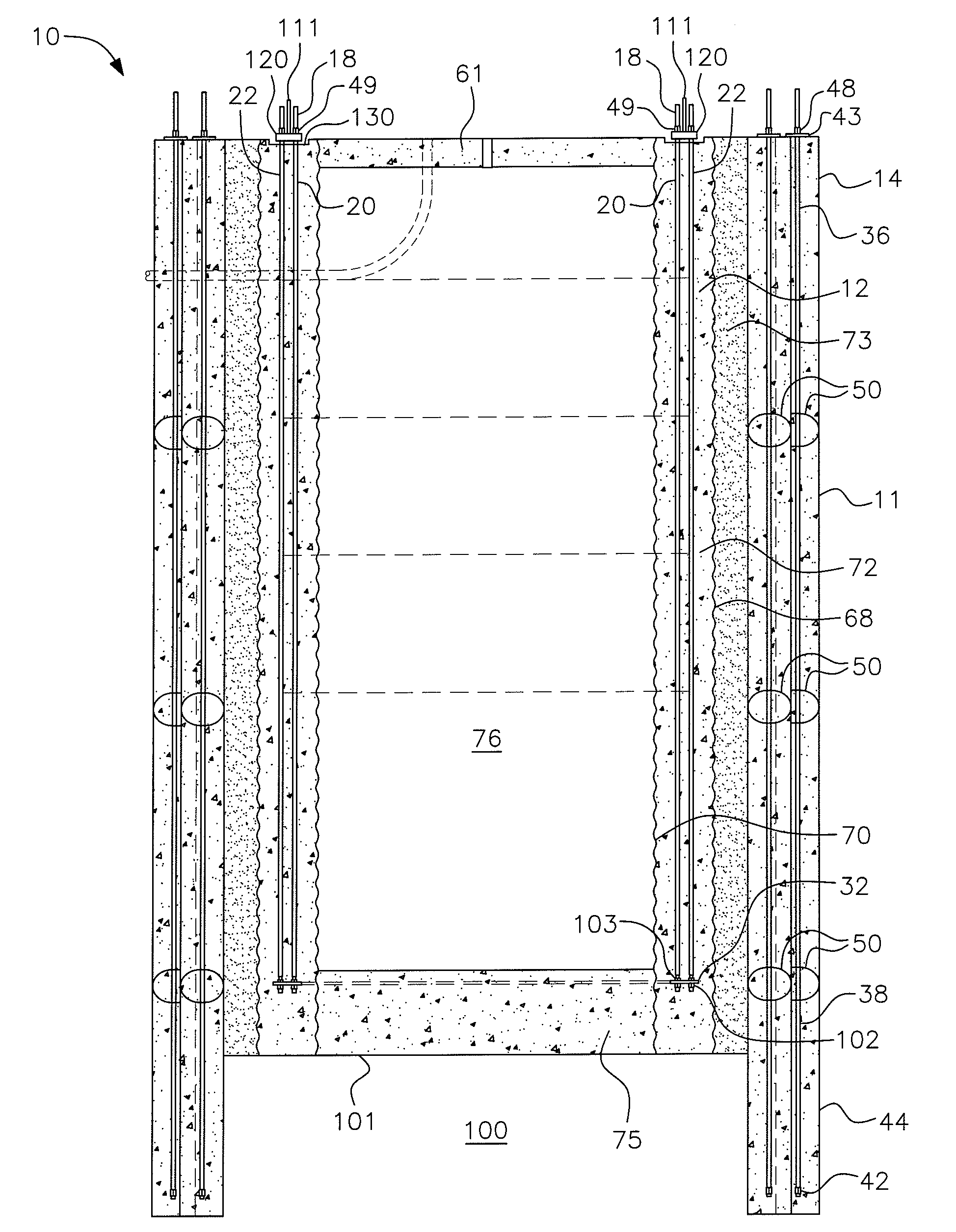
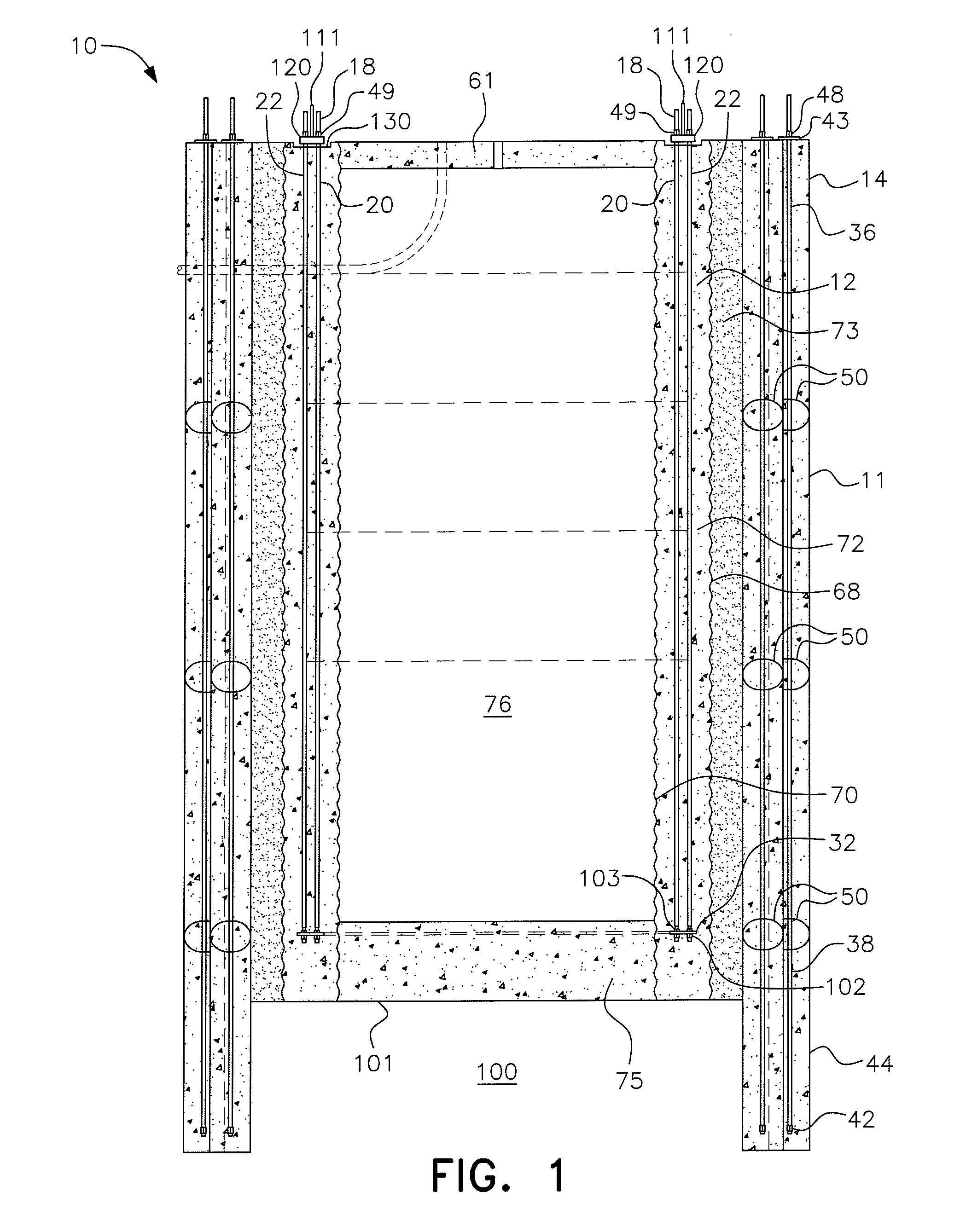
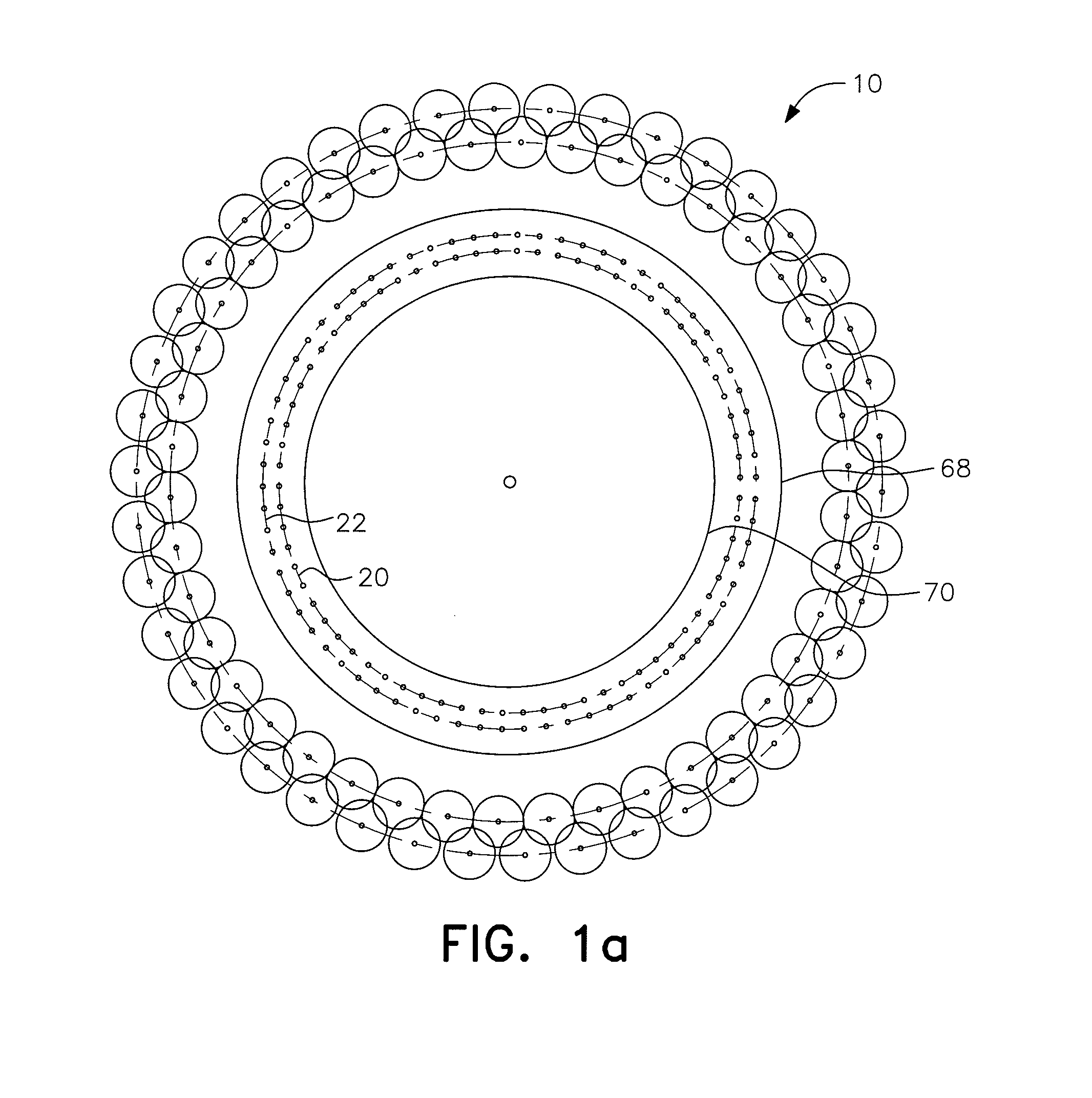
[0044]a perimeter pile anchor foundation in accordance with the present invention is shown in FIGS. 1, 1a and 2. The perimeter pile anchor foundation, generally designated by reference numeral 10, has a plurality of pile anchors or “piles”, each generally designated by the reference numeral 14 extending vertically downward into the soil 100 and forming a perimeter wall, generally designated by reference numeral 11, for the foundation 10. The pile anchors 14 thus serve to secure the concrete foundation 10 into the ground. A first or outer CMP 68 is placed vertically in the excavation inside the perimeter wall 11 to form an outer annular ring, generally designated by reference numeral 73, between the inside of the perimeter wall 11 and the outer CMP 68.

[0045]According to the first embodiment, a second or inner CMP 70 is placed inside the outer CMP 68, forming an inner annular ring, also referred to herein as the foundation ring 72. Extending through the concrete foundation ring 72 is ...

second embodiment

[0067] shown in FIG. 10, after the pile anchors are formed, only an inner CMP 70 is vertically placed inside the pile perimeter and spaced therefrom to create an annular foundation ring 80 between the CMP 70 and the piles 14. A direct embedded section, generally designated by reference numeral 85, is placed near the top of the foundation ring 80. The direct embedded section 85 includes a generally U-shaped reinforcing steel cage, generally designated by reference numeral 87, formed by a loop of rebar coupled with a structure extension, generally designated by reference numeral 116, which is shown in FIG. 11. The cage 87 is constituted by a piece of rebar bent to have a generally vertical inner leg 88 and a generally vertical outer leg 89 joined at the top by a generally horizontal length 90 of the rebar extending through holes 110 in the generally cylindrical side wall 112 of the extension 116 of the embedded section 85 to form the generally U-shaped configuration for cage 87. Rebar...


PUM


Abstract

A perimeter pile anchor foundation is built by forming a plurality of individual perimeter pile anchors in a large generally circular pattern to form a perimeter wall. The individual pile anchors are contiguous, each pile overlapping the adjacent piles on either side. The overlapping pile anchors form an arch such that compression and friction between the pile anchors resist soil caving and sloughing pressure when soil inside the perimeter wall is excavated, enabling the perimeter pile foundation to be effectively constructed in weak saturated soils and/or cohesionless sands that will not allow conventional concrete foundation excavations. A concrete foundation ring is formed inside the pile perimeter wall to support a tall and/or heavy tower or other structure subject to high upset forces.

Description

BACKGROUND OF THE INVENTION[0001]1. Field of the Invention[0002]The present invention is related to the field of pile anchor foundations for supporting tall, heavy and / or large towers or the like which can be subject to high upset forces. More particularly, the present invention is directed to a perimeter pile anchor foundation including a plurality of pile anchors drilled in a circular or generally circular pattern so that adjacent piles overlap and form an arch with compression between the piles to resist soil caving in weak soils.[0003]2. Description of the Related Art[0004]In known pile anchor foundations, the piles extend downwardly from a foundation cap into the underlying soil and are spaced from one another. Such foundations are limited by soil conditions, as weak or wet soils will cave or sluff when, during construction, the ground under the center of the cap is excavated vertically.[0005]Various forms of concrete foundations utilizing operational features of the instant in...

Claims


Application Information

Patent Timeline
IPC IPC(8): E02D5/38
CPCE02D5/38E02D27/12E02D5/34E02D27/425E02D2250/0007E02D2250/0023E02D2300/002E02D2300/0045
Inventor HENDERSON, ALLAN P.
Owner TERRACON CONSULTANTS INC
Why Eureka
Try Eureka