Indirect Bonding Tray and Method of Manufacture Thereof

a technology of direct bonding and tray, which is applied in the field of orthodontics, can solve the problems of prolonged treatment time, unintended arch wire bending or the need for bracket repositioning during treatment,

Inactive Publication Date: 2014-09-11
AMERICAN ORTHODONTICS
View PDF2 Cites 43 Cited by
  • Summary
  • Abstract
  • Description
  • Claims
  • Application Information

AI Technical Summary

Benefits of technology

[0004]Available indirect bonding trays also generally limit access to bracket pads during the bonding process which can present challenges for orthodontists to create clean and reliable bonds on all of the brackets applied to a patient's teeth.

Problems solved by technology

Incorrect bracket placement often leads to unintended arch wire bending or the need for bracket repositioning during treatment.
These intra-treatment procedures are time consuming clinically and can lead to prolonged treatment times.
Available indirect bonding trays also generally limit access to bracket pads during the bonding process which can present challenges for orthodontists to create clean and reliable bonds on all of the brackets applied to a patient's teeth.

Method used


Image

  • Indirect Bonding Tray and Method of Manufacture Thereof
  • Indirect Bonding Tray and Method of Manufacture Thereof
  • Indirect Bonding Tray and Method of Manufacture Thereof

Examples


Embodiment Construction

[0017]Indirect bonding trays as disclosed herein and the methods of manufacturing such trays can be used by dental professionals to precisely place orthodontic brackets and / or create customized composite bases for orthodontic brackets placed in a direct or indirect manner.

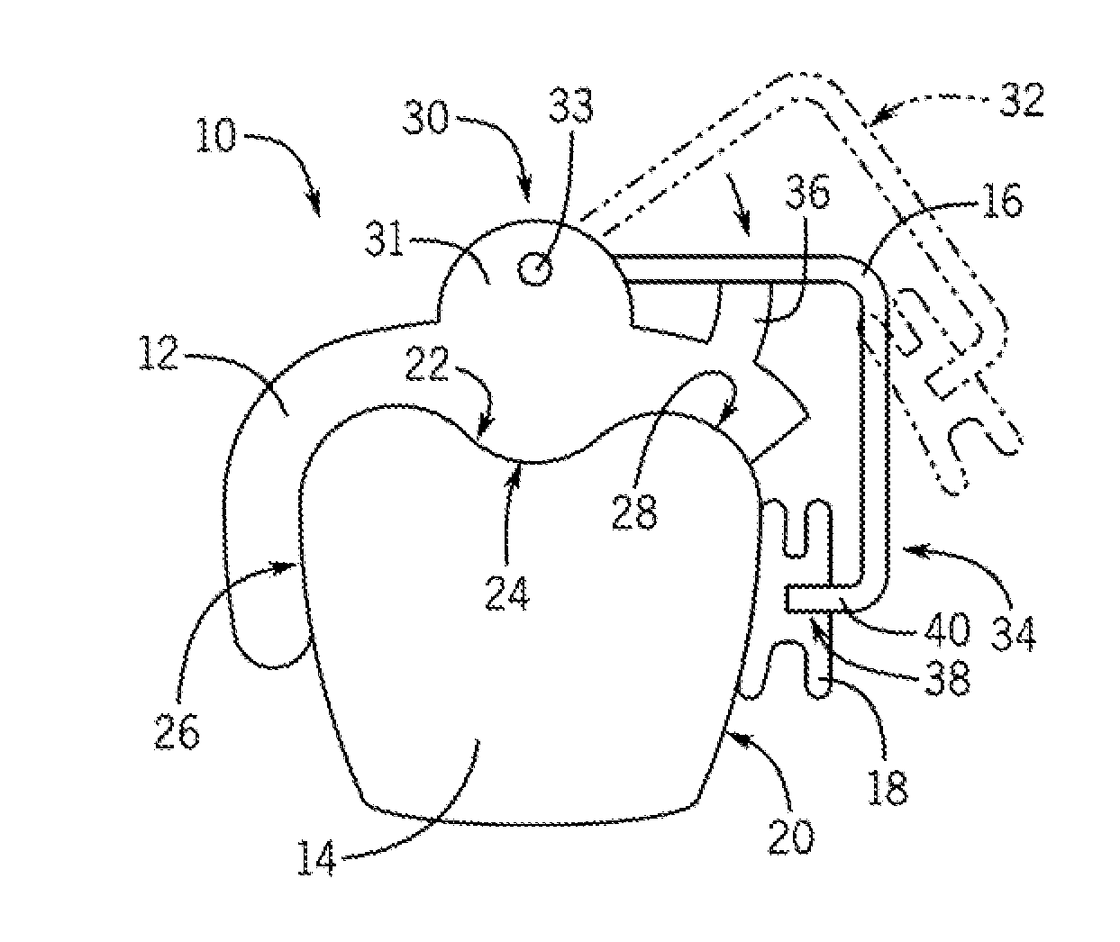
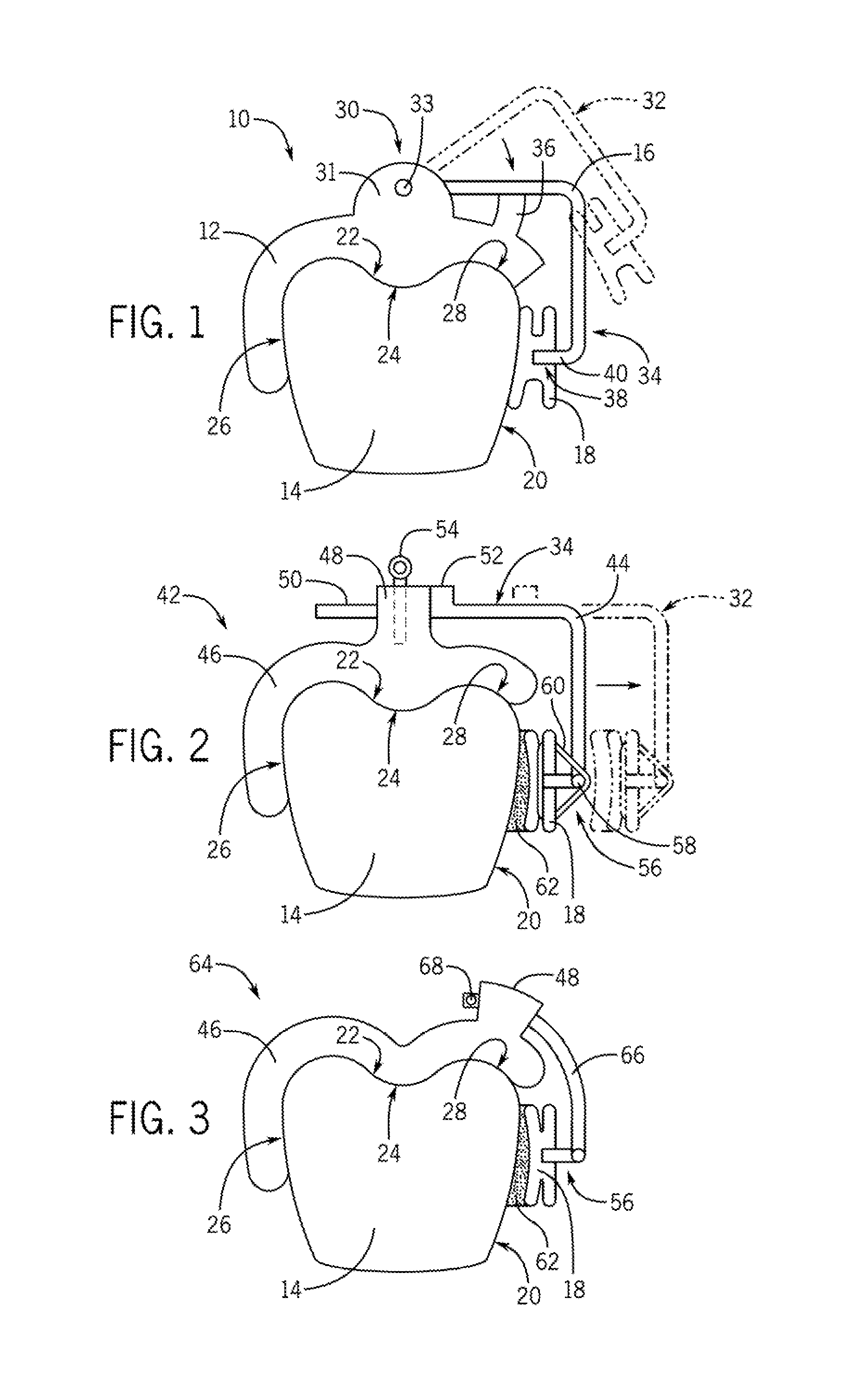
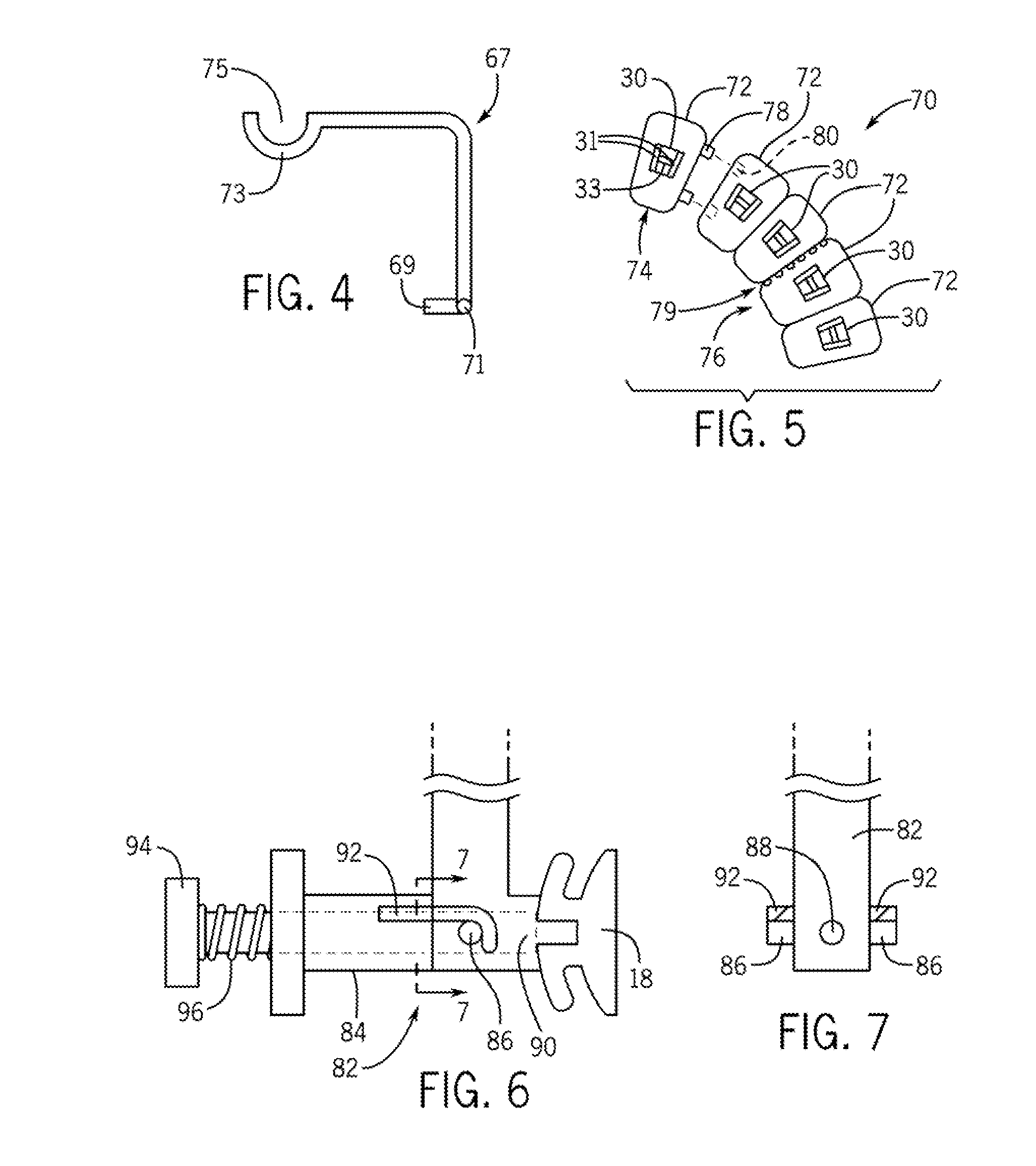
[0018]FIGS. 1-7, as will be described in greater detail herein, present various embodiments of indirect bonding trays which in some embodiments may be constructed according to the method as disclosed herein with respect to FIG. 8. Still further embodiments of indirect bonding trays may be used in accordance with the method 200 of using an indirect bonding tray to construct customized composite bases depicted in the flow chart of FIG. 9. FIG. 8 is a flow chart that depicts an embodiment of a method 100 of manufacturing an indirect bonding tray. At 102 a three-dimensional digital model of the patient's pre-treatment dentition is obtained. This 3D digital model may be obtained in a variety of ways including, but not l...


PUM


Abstract

An indirect bonding tray includes a least on tooth position each tooth portion includes an occlusal surface that conforms to an occlusal surface of an associated tooth of a patient's dentition. At least one of bracket arm includes a bracket arm tip configured to engage an orthodontic bracket. The at least one bracket arm movably attached to at least one tooth portion to move between a first position and second position relative to a bonding surface of the associated tooth. In the second position, the bracket arm is in a position configured to hold an orthodontic bracket in a predetermined treatment position relative to the bonding surface of the associated tooth.

Description

CROSS-REFERENCE TO RELATED APPLICATION[0001]The present application claims priority of U.S. Provisional Patent Application No. 61 / 773,404, filed on Mar. 6, 2013, the content of which is hereby incorporated herein by reference in its entirety.BACKGROUND[0002]The present disclosure relates to the field of orthodontics. More specifically, the present disclosure relates to a tray for use in an indirect bonding method of orthodontic bracket application, and a method of manufacturing such a tray.[0003]Orthodontic brackets can be bonded to a patient's teeth by an orthodontist either through a direct method in which the orthodontist manually bonds each bracket one at a time to each of the patient's teeth or through an indirect method in which a bonding tray holds and seats multiple brackets to the patient's teeth. While the indirect bonding technique offers some alignment verification through the use of the tray, bracket placement through either manual or indirect bonding techniques is dete...

Claims


Application Information

Patent Timeline
Patent Type & Authority Applications(United States)
IPC IPC(8): A61C7/14
CPCA61C7/146
Inventor MACHATA, WILLIAM CHARLESMARSHALL, MICHAEL CRAIG
Owner AMERICAN ORTHODONTICS
Why Eureka
Try Eureka