Ball screw device

a ball screw and screw technology, applied in the direction of gearing, gearing elements, hoisting equipment, etc., can solve the problems of reducing the size of the ball screw device, and limiting the paired deflectors

Active Publication Date: 2014-09-18
JTEKT CORP
View PDF20 Cites 30 Cited by
  • Summary
  • Abstract
  • Description
  • Claims
  • Application Information

AI Technical Summary

Benefits of technology

[0007]If the positions in the circumferential direction, where deflectors are arranged, are not limited, the theoretically effective number of the turns of a ball screw device can be employed as it is. Consequently, it is possible to reduce the size of the ball screw device in the axial direction.

Problems solved by technology

However, if the through-hole is limited to the one that extends along the axial direction, the positions in the circumferential direction, where the paired deflectors (the feed-side deflector member and the discharge-side deflector member) are arranged, are limited.
Therefore, there is a possibility that the ball screw device becomes larger than necessary in the axial direction.

Method used


Image

  • Ball screw device
  • Ball screw device
  • Ball screw device

Examples


first embodiment

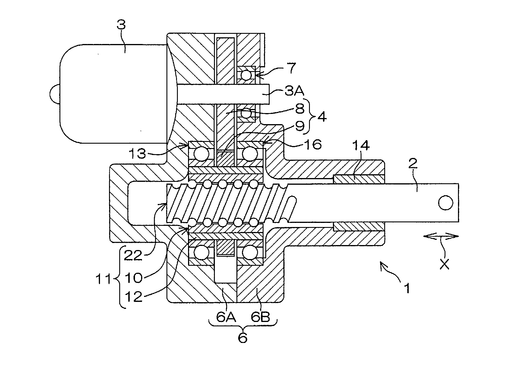
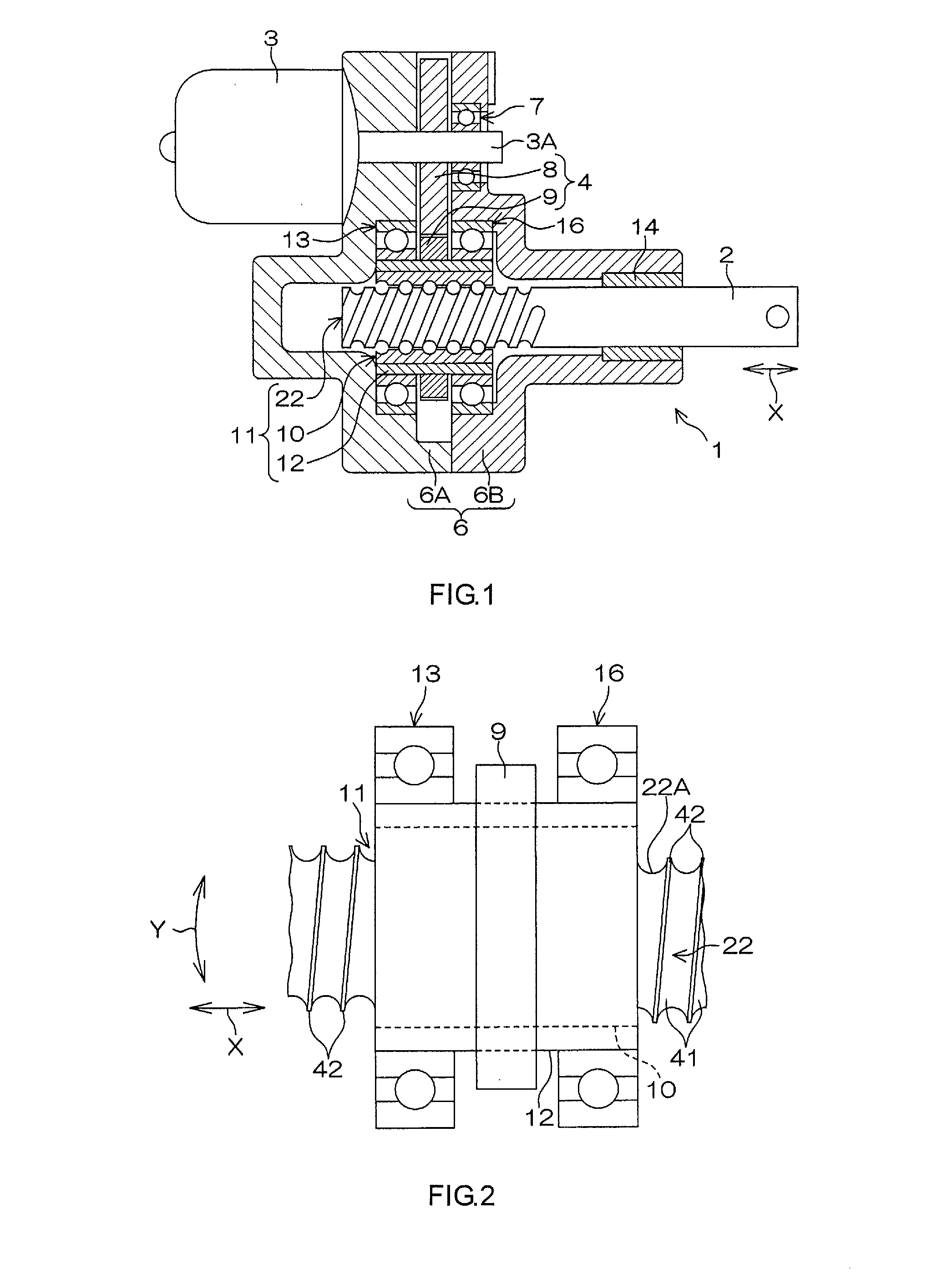
[0040]Hereinafter, example embodiments of the invention will be described with reference to the accompanying drawings. FIG. 1 is a schematic sectional view of an electric actuator 1 to which a ball screw device 11 according to the invention is applied. The electric actuator 1 moves a drive shaft 2 back and forth in an axial direction X to drive an object to be driven.

[0041]The electric actuator 1 includes: an electric motor 3; the drive shaft 2; a speed reduction mechanism 4 that transmits rotary torque output from the electric motor 3; the ball screw device 11 that converts the rotary torque output from the electric motor 3 and transmitted via the speed reduction mechanism 4, into a linear motion of the drive shaft 2 in the axial direction X; and a housing 6 in which the drive shaft 2, the speed reduction mechanism 4 and the ball screw device 11 are accommodated. The housing 6 has a first housing 6A, and a second housing 6B brought into contact with an end face of the first housing...

second embodiment

[0077]FIG. 13 is an exploded perspective view of a ball screw device 311 according to the invention. FIG. 14 is a schematic vertical sectional view of the ball screw device 311. FIG. 13 illustrates the configuration of the ball screw device 311 from which the threaded shaft 22 is omitted. The ball screw device 311 is applied to, for example, an electric actuator equivalent to the electric actuator 1 described with reference to FIG. 1.

[0078]In the second embodiment, the same portions as those in the first embodiment will be denoted by the same reference symbols as those in FIG. 1 to FIG. 9, and description thereof will be omitted. As illustrated in FIG. 13 and FIG. 14, the ball screw device 311 includes the threaded shaft 22, the ball nut 10 fitted onto the threaded shaft 22, a plurality of balls 24 interposed between the threaded shaft 22 and the ball nut 10, a cylinder 312 that surrounds the outer periphery of the ball nut 10, and a pair of deflectors 340. The ball screw device 311...

third embodiment

[0107]FIG. 21 is an exploded perspective view of a ball screw device 411 according to the invention. FIG. 22 and FIG. 23 are schematic vertical sectional views of the ball screw device 411. FIG. 21 illustrates the configuration of the ball screw device 411 from which the threaded shaft 22 is omitted. The ball screw device 411 is applied to, for example, an electric actuator equivalent to the electric actuator 1 described with reference to FIG. 1.

[0108]In the third embodiment, the same portions as those in the first embodiment will be denoted by the same reference symbols as those in FIG. 1 to FIG. 9, and description thereof will be omitted. As illustrated in FIG. 21 to FIG. 23, the ball screw device 411 includes the threaded shaft 22, a ball nut 410 fitted onto the threaded shaft 22, a plurality of balls 24 interposed between the threaded shaft 22 and the ball nut 410, a cylinder 412 that surrounds the outer periphery of the ball nut 410, a pair of deflectors 440, and a key fitting ...


PUM


Abstract

A ball screw device includes a cylinder that surrounds the outer periphery of a ball nut. Accommodation holes are formed in the ball nut at a rolling start position and a rolling end position in ball rolling paths. An outer periphery turning groove is formed in an outer peripheral face of the ball nut, and the outer periphery turning groove and an inner peripheral face of the cylinder constitute a turning rolling path. The turning rolling path and connection passages formed in deflectors constitute a circulation path through which balls are returned from the rolling end position to the rolling start position.

Description

INCORPORATION BY REFERENCE[0001]The disclosures of Japanese Patent Applications No. 2013-49193 and No. 2013-107273 respectively filed on Mar. 12, 2013 and May 21, 2013, each including the specification, drawings and abstract, are incorporated herein by reference in their entireties.BACKGROUND OF THE INVENTION[0002]1. Field of the Invention[0003]The invention relates to a ball screw device.[0004]2. Description of the Related Art[0005]A ball screw device described in Japanese Patent Application Publication No. 2010-71411 (JP 2010-71411 A) has a circulation path that provides communication between one end portion and the other end portion of a ball rolling path to allow balls to circulate along a raceway. The circulation path has a through-hole formed so as to pass through a peripheral wall of a ball nut in its axial direction, a feed-side communication passage that provides communication between one end of the through-hole and the one end portion of the ball rolling path, and a discha...

Claims


Application Information

Patent Timeline
Patent Type & Authority Applications(United States)
IPC IPC(8): F16H25/22
CPCF16H25/2204F16H25/2214F16H2025/2271Y10T74/19744
Inventor SAKAGUCHI, NAOKOTASHIRO, AKIYOSHI
Owner JTEKT CORP
Why Eureka
Try Eureka