Socket with four point drive

a four-point drive, socket technology, applied in the field of sockets, can solve the problems of more failures of sockets at the socket end, increased demands on sockets that are required to torque these fasteners, and failure of sockets, so as to reduce stress concentration, minimize the likelihood of failure, and improve the effect of li

Active Publication Date: 2014-09-18
WRIGHT TOOL
View PDF5 Cites 12 Cited by
  • Summary
  • Abstract
  • Description
  • Claims
  • Application Information

AI Technical Summary

Benefits of technology

[0015]In another aspect of the invention, a provision is provided wherein the curved recess surfaces comprise adjacent pairs of arcuate recess surfaces being disposed on opposite sides of a curved corner apex surface. The curved corner apex surface may be defined by an opening corner diameter, which may be the diameter of the circle that inscribes the inner corners of the drive end opening. The arcuate recess surfaces may each be defined by a corner radius provided for minimizing stress concentration at the inner corners.
[0025]Another object of an embodiment of the invention is to improve the drive end of spline sockets that experience enhanced forces and greater stress concentrations compared to other socket designs, and which may be more likely to fracture due to being harder and having less ductility than other sockets.

Problems solved by technology

Although the standards for the socket ends are well established, they typically only govern the clearance and tolerance requirements for the various types of sockets, and do not control other design considerations, such as sharp inner corners that may act as stress risers leading to failure of the socket.
Although early hexagonal sockets that were turned by hand did not usually have problems with failure at the corners, the introduction of higher strength fasteners and impact wrenches with enhanced torque loads resulted in more failures of sockets at the socket end.
These failures were often caused by stress concentration of the increased loads at the sharp inner corners.
As such, the demands on the sockets that are required to torque these fasteners have also increased.
Thus, spline sockets have a reactant force vector that is parallel to the vector of force that drives the socket, resulting in more productive loads on the fastener, but which also results in greater stress on the socket body.
The greater resultant forces in spline sockets not only affect the socket end that engages the fastener, but the forces affect the drive end of the socket as well.
However, the standard does not control design considerations such as sharp inside corners that may act as stress risers.
Thus, prior art spline sockets have been known to fracture at the drive end, or in some instances explode due to the enhanced loads that they experience, which is caused by the increased stress concentration at the sharp inner corners of the drive end of the socket.
While the Wright Drive® improvement was very helpful for the socket end of a socket wrench, no one had previously considered a similar improvement to the drive end in the over 25 years that this improved design has been employed.
More particularly, the drive end of sockets has not been improved in a similar manner in at least the 60 years since hexagonal sockets were developed.
In addition, the drive anvil (or drive square) that engages the socket is usually harder and stronger than the material composing the socket body, which can cause excessive wear and stress on the drive end of the socket that is receiving the torque load.
These rapid, high-energy bursts can damage the socket at the drive end, and where these bursts of energy are repetitiously delivered at the stress-riser of a sharp corner, premature failure of the socket may occur.
High quality sockets, particularly those spline sockets of a large size, can be very expensive.

Method used


Image

  • Socket with four point drive
  • Socket with four point drive
  • Socket with four point drive

Examples


Embodiment Construction

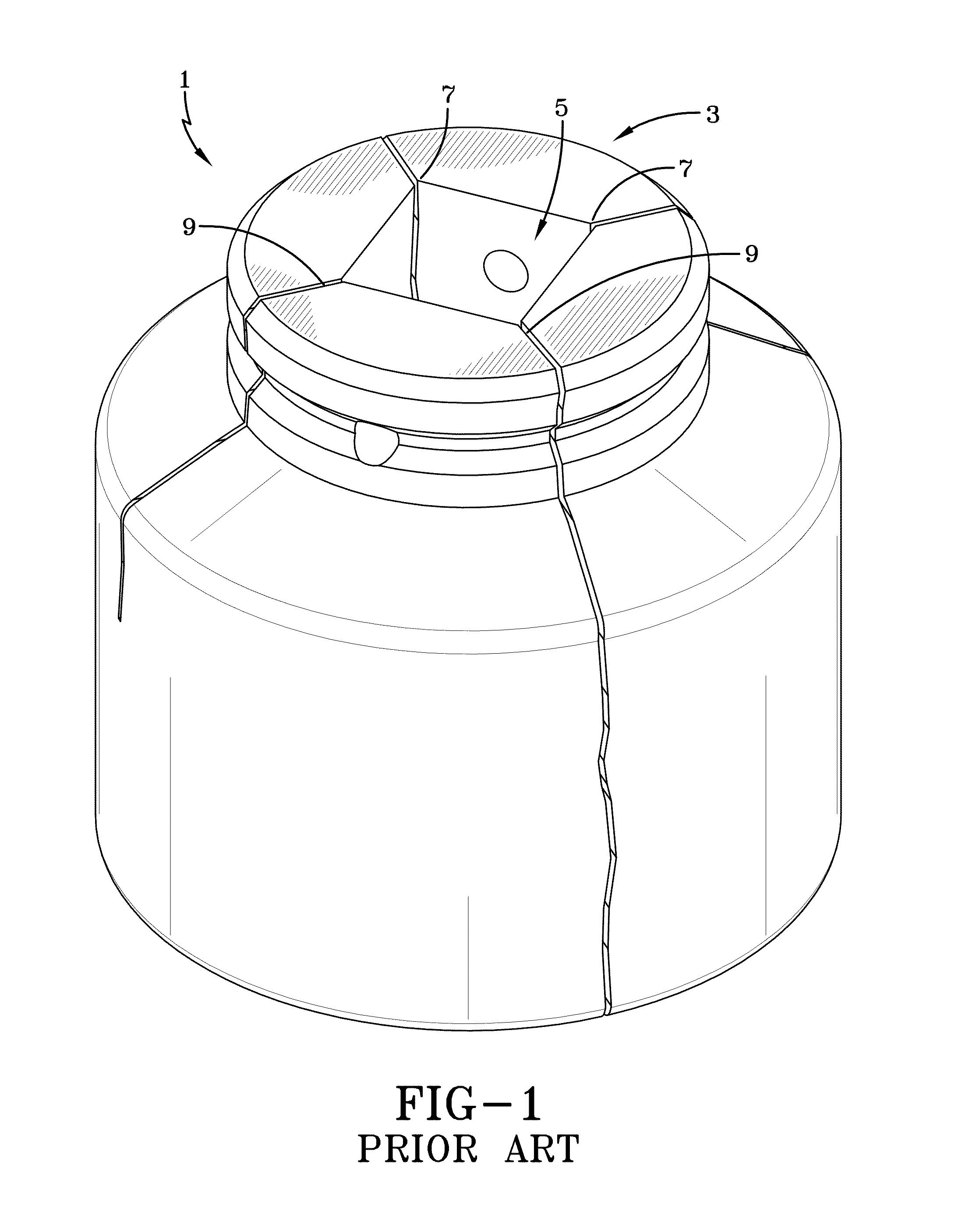
[0037]As explained in the background of the invention, the inside corners in the drive end opening of sockets have heretofore been sharp corners which results in stress risers at those corners. When high torque loads are applied to the drive end of a socket, the stress concentrated at these inner corners may exceed the yield strength or tensile strength of the socket material leading to failure, which can include plastic deformation or fracture. A schematic diagram of a prior art spline socket 1 illustrating fractures 9 at the sharp inside corners 7 of a drive end opening 5 are depicted in FIG. 1. These types of fractures 9 at the drive end 3 of prior art sockets are well known, particularly with respect to spline sockets that experience enhanced loading due to the particular distribution of forces in a spline socket torque application.

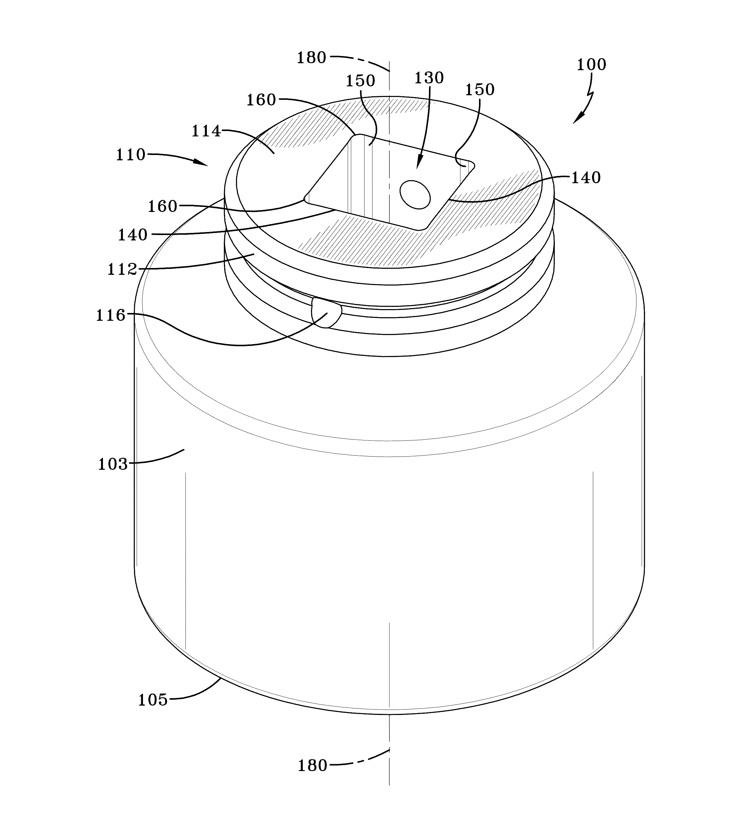
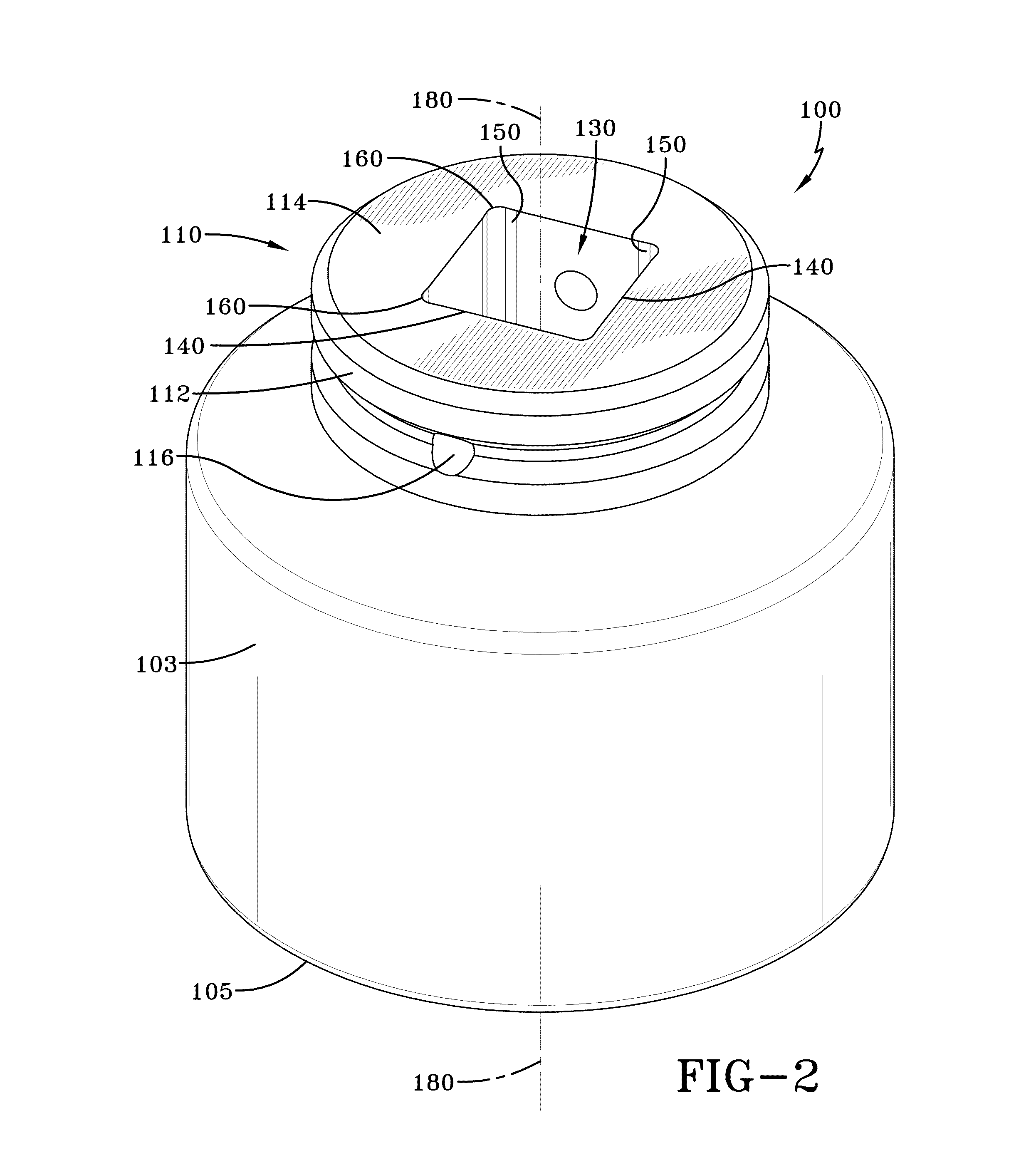
[0038]The present invention is directed toward improving the opening in the drive end of sockets for preventing failure of the socket during a torque...


PUM


Abstract

An improved socket having a drive end opening being so dimensioned for receiving a drive anvil, the opening comprising a plurality of bounding surfaces parallel to a central axis and being disposed in diametrically opposed pairs about the axis, where the diametrically opposed pairs of bounding surfaces include: at least two pairs of flat side surfaces being parallel to each other about the central axis; at least two pairs of curved recess surfaces forming respective inner corners of the drive end opening; and adjacent pairs of outwardly diverging transition surfaces transitioning between respectively adjacent pairs of the flat side surfaces and the curved recess surfaces. The improved socket increases corner radius for minimizing stress concentration at the corners and provides outwardly diverging transition surfaces for relocating the areas of maximum stress away from the corners.

Description

CROSS-REFERENCE TO RELATED APPLICATIONS[0001]This application claims priority to U.S. Provisional Application Ser. No. 61 / 794,415, filed Mar. 15, 2013, which is incorporated herein by reference in its entirety.BACKGROUND OF THE INVENTION[0002]1. Field of the Invention[0003]This invention relates to sockets, and in particular to improvements in the drive end of sockets.[0004]2. Discussion of the Prior Art[0005]The first socket wrench was patented by J. J. Richardson in 1863 (U.S. Pat. No. 38,914). Early socket wrenches of this type were developed with square socket heads since hand filing was the typical method of manufacture in this era. However, with the advancement of modern manufacturing techniques, such as milling, shaping, broaching and die forging, sockets having hexagonal heads were developed and became more common. For over sixty years, sockets for hexagonal fasteners have been made having two styles of socket end openings, a six-point opening and a twelve-point opening, the...

Claims


Application Information

Patent Timeline
Patent Type & Authority Applications(United States)
IPC IPC(8): B25B13/06B25B23/00
CPCB25B23/0035B25B13/06B25B13/065
Inventor MILLIGAN, KENNETH R.TAYLOR, TERRY G.
Owner WRIGHT TOOL
Why Eureka
Try Eureka