
Blow molding device and blow molding method

Inactive Publication Date: 2014-09-18
FTS
View PDF3 Cites 6 Cited by
  • Summary
  • Abstract
  • Description
  • Claims
  • Application Information

AI Technical Summary

Benefits of technology

The invention is a blow molding device and method that can make a product with a built-in part that has a good yield rate.

Problems solved by technology

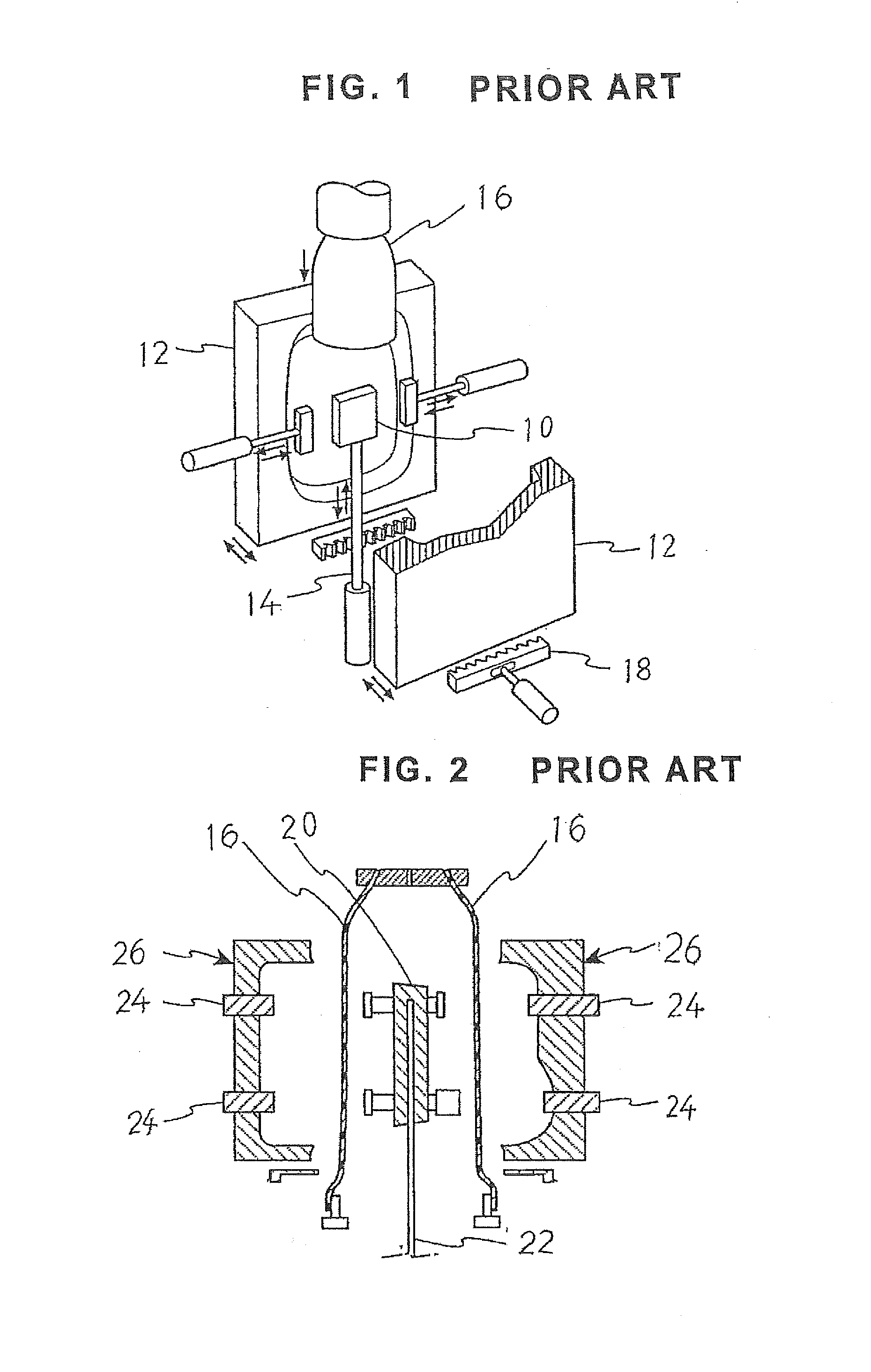
But, when the diameter of the parison 16 increases, the parison 16 is extruded exceeding a required amount for forming the blow molded article, and as a result, the amount of flash around the resulted blow molded article increases to cause a waste of material.

Method used


Image

  • Blow molding device and blow molding method
  • Blow molding device and blow molding method
  • Blow molding device and blow molding method

Examples


Embodiment Construction

[0072]Hereinafter, an embodiment of a blow molding device of the present invention will be explained based on a blow molding device adapted to form a fuel tank for use in a motor vehicle, as a blow molded article with reference to FIG. 3 through FIG. 14. The present invention will be explained with reference to the blow molding device for forming a fuel tank having a built-in part, but can be applied to another blow molded article having another built-in part.

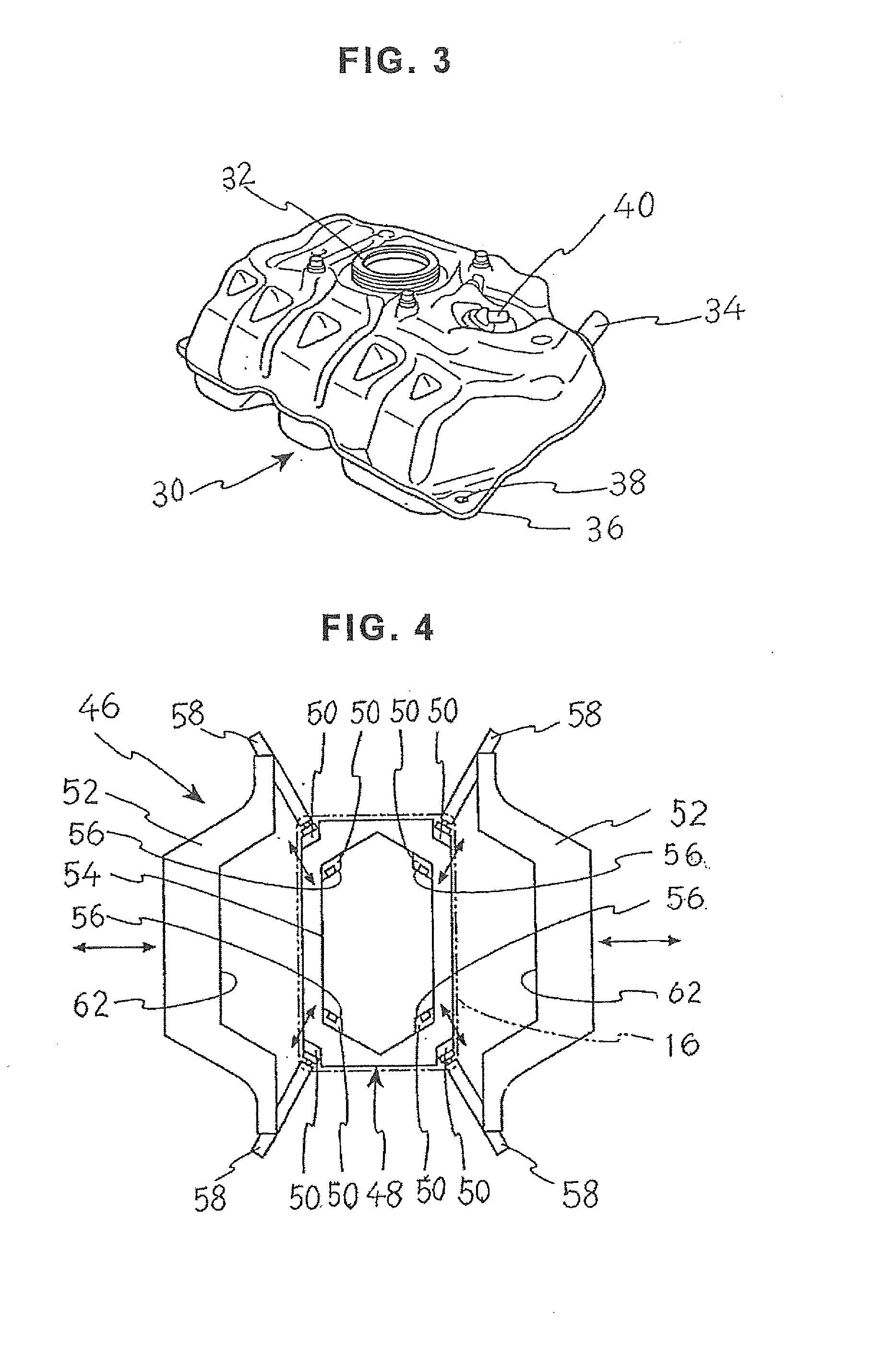
[0073]FIG. 3 is a perspective view of a fuel tank 30 that is formed using a blow molding device of the present embodiment.

[0074]As shown in FIG. 3, the fuel tank 30 formed with the blow molding device of the present embodiment has a pump unit mounting hole 32 for mounting a fuel pump (not shown) on the fuel tank 30 in an upper surface thereof. And, a fuel inlet hole 34 is provided in a side surface or the upper surface of the fuel tank 30 for injecting fuel from an inlet pipe (not shown).

[0075]And, an outer circumferential rib ...


PUM


Abstract

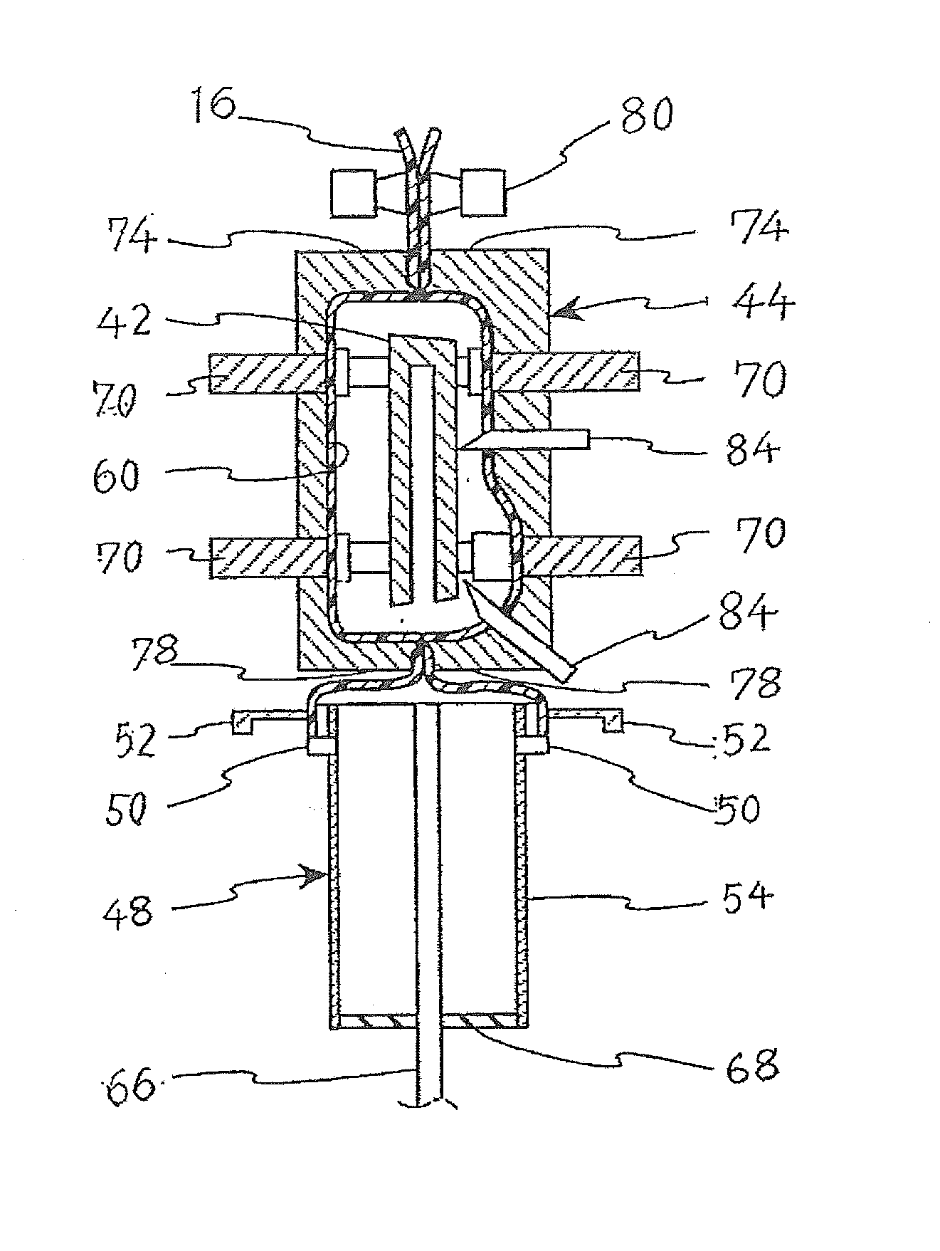
A blow molding device capable of forming a blow molded article having a built-in part with a good yield rate, and a blow molding method. The blow molding device has a blow mold, a parison holding unit and a built-in part holding unit. The parison holding unit has parison expanders and a parison outer holding plate. The built-in part holding unit has an airtight guide tube and a holding rod. After a lower end of a parison is expanded with a plurality of parison expanders, and an upper end of the airtight guide tube is inserted in the lower end of the parison, the lower end of the parison is held between the upper end of the airtight guide tube and the parison outer holding plate, and the preblowing is carried out. After the built-in part is positioned in an interior space of the parison, and the parison and built-in part are held with the slide cores, the holding rod is removed from the blow mold.

Description

CROSS-REFERENCE TO RELATED APPLICATION[0001]This application is related to and claims priority from Japanese patent application No. 2011-210979 incorporated herein by reference.BACKGROUND OF THE INVENTION[0002]1. Field of the Invention[0003]The present invention relates to a blow molding device adapted to form a blow molded article having a built-in part composed of a thermoplastic synthetic resin in an interior space thereof, and a blow molding method.[0004]2. Description of Related Art[0005]Conventionally, tubular blow molded articles, such as fuel tanks for use in motor vehicles, etc., have been formed of metal, but, in recent years, thermoplastic synthetic resins have been frequently used to form such tubular blow molded articles, because they can effect lightweight vehicle bodies, no rust is generated therein, and they can be readily formed into desired configurations.[0006]In many cases, the tubular articles made of thermoplastic synthetic resins have been formed by blow moldi...

Claims


Application Information

Patent Timeline
IPC IPC(8): B29C49/20
CPCB29C49/20B29L2031/7172B29C49/04B29C49/4247B29C49/4817B29C2049/2013B29C2049/2078B29C2049/4807B29C2049/481B29C2049/6063B29C2049/609
Inventor MAJIMA, TAKAHISAASAHARA, TOSHIAKISUGIURA, KOJI
Owner FTS
Learn More