
Scale for photoelectric encoder

a technology of photoelectric encoder and scale, which is applied in the direction of instruments, optical elements, mountings, etc., can solve the problems of poor adhesion to sus, difficult to maintain the quality of graduated marks, and limited etched scale structure, etc., and achieves the effect of convenient configuration and reduced cos

Active Publication Date: 2014-12-18
MITUTOYO CORP
View PDF7 Cites 3 Cited by
  • Summary
  • Abstract
  • Description
  • Claims
  • Application Information

AI Technical Summary

Benefits of technology

The present patent provides a cheaper and more reliable photoelectric encoder, with improved accuracy. This is achieved by a scale having a low-reflection surface and a higher reflectance light reflection surface, ensuring accurate measurements. The method of forming the scale is simple and cost-effective. Overall, the invention allows for a more cost-effective and reliable production of photoelectric encoders.

Problems solved by technology

The etched scale structure can be fondled at a low cost; however, an etching resist (photoresist) forming graduated marks on the SUS surface, i.e., used in a lithography technique, has poor adhesion to SUS and quality of the graduated marks is difficult to maintain.
Thus, particularly when used on a long article, the etched scale structure has been limited, such as having an accommodatable length of the scale become shorter and having low yield rates.
In addition, in the technology disclosed in Japanese Patent Laid-open Publication No. 2009-264923, a DLC film must be deposited on the surface of the substrate of the scale, which may become expensive.

Method used


Image

  • Scale for photoelectric encoder
  • Scale for photoelectric encoder
  • Scale for photoelectric encoder

Examples


Embodiment Construction

[0025]The particulars shown herein are by way of example and for purposes of illustrative discussion of the embodiments of the present invention only and are presented in the cause of providing what is believed to be the most useful and readily understood description of the principles and conceptual aspects of the present invention. In this regard, no attempt is made to show structural details of the present invention in more detail than is necessary for the fundamental understanding of the present invention, the description taken with the drawings making apparent to those skilled in the art how the forms of the present invention may be embodied in practice.

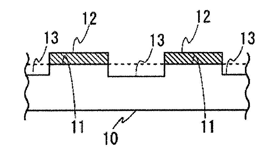
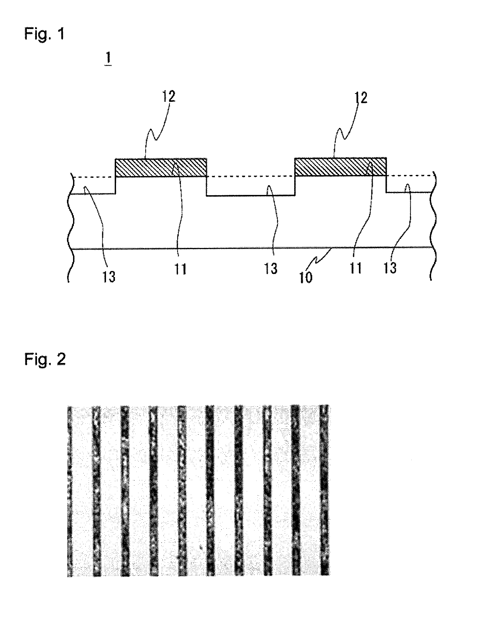
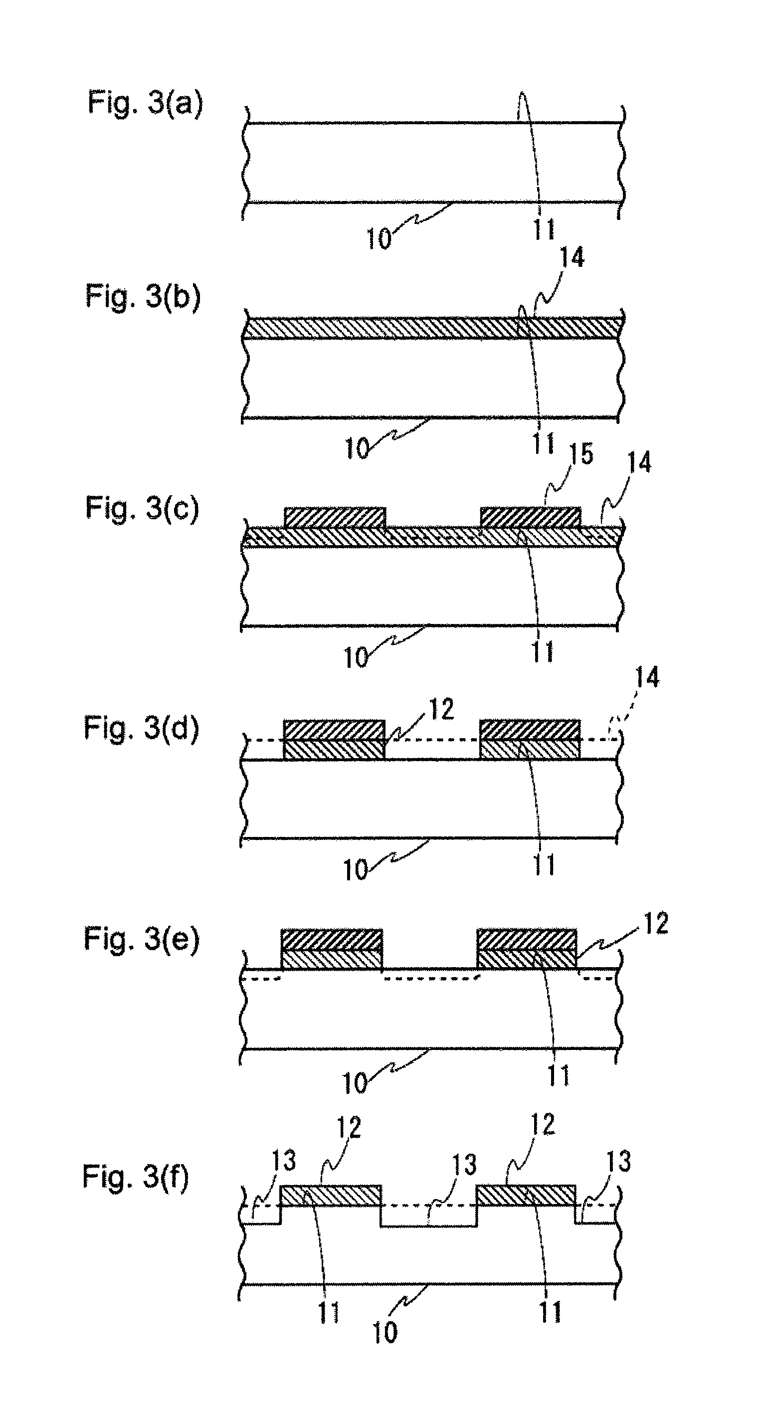
[0026]Hereafter, an embodiment of the present disclosure is described with reference to the drawings. FIG. 1 illustrates a partial cross-sectional view of a scale according to an embodiment of the present disclosure. FIG. 2 is an expanded view of a portion of a scale 1. The scale 1 includes a light reflection surface 12 formed by...


PUM

PropertyMeasurementUnit
thicknessaaaaaaaaaa
wavelengthsaaaaaaaaaa
reflectionaaaaaaaaaa

Abstract

A scale for a photoelectric encoder includes a scale substrate and a reflection film formed at a predetermined pitch on the scale substrate. A surface of the reflection film forms a reflection surface. A low-reflection surface is formed by etching the scale substrate between reflection films. Accordingly, a scale can be provided which is lower in cost and has favorable yield rates.

Description

CROSS-REFERENCE TO RELATED APPLICATIONS[0001]The present application claims priority under 35 U.S.C. §119 of Japanese Application No. 2013-125161, filed on Jun. 14, 2013, the disclosure of which is expressly incorporated by reference herein in its entirety.BACKGROUND OF THE INVENTION[0002]1. Field of the Invention[0003]The present invention relates to a scale for a photoelectric encoder, an encoder, and a method of forming a scale.[0004]2. Description of Related Art[0005]Several methods are known of forming a scale for a photoelectric encoder. One of the methods of forming the scale is a method of etching SUS (Special Use Stainless Steel), which serves as a substrate of the scale (a scale having a structure formed with this method is referred to hereafter as an etched scale structure).[0006]FIG. 6 illustrates a partial cross-sectional view of a scale 100 having the etched scale structure. In order to facilitate understanding, cross-hatching of the substrate is omitted in the cross-s...

Claims


Application Information

Patent Timeline
Patent Type & Authority Applications(United States)
IPC IPC(8): G01D5/347
CPCG01D5/34746G01D5/34707
Inventor MAEDA, FUJIO
Owner MITUTOYO CORP
Learn More