Manufacturing method of fan stator structure

a manufacturing method and technology of a fan, applied in the direction of manufacturing dynamo-electric machines, dynamo-electric machines, electrical apparatus, etc., can solve the problems of tin leakage and large weld nuggets, and consuming a lot of time and labor, so as to reduce the time and labor needed, reduce the manufacturing cost, and improve the effect of production efficiency

Pending Publication Date: 2022-04-14
ASIA VITAL COMPONENTS (CHINA) CO LTD
View PDF7 Cites 0 Cited by
  • Summary
  • Abstract
  • Description
  • Claims
  • Application Information

AI Technical Summary

Benefits of technology

[0012]With the manufacturing method of fan stator structure according to the present invention, it is possible to largely reduce the time and labors needed to manufacture the fan stator, reduce the manufacturing costs, and upgrade the production efficiency and good yield rate.

Problems solved by technology

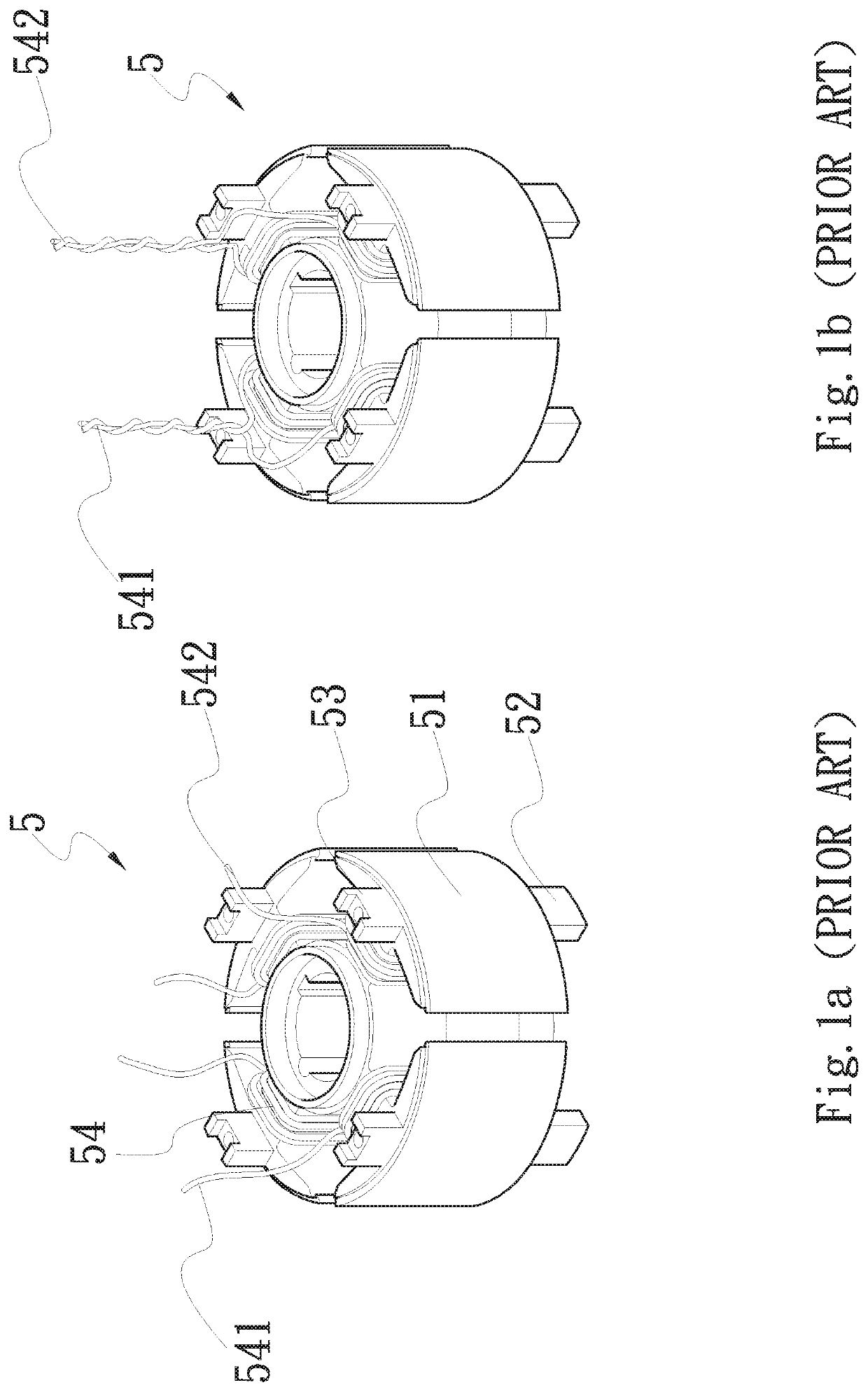
According to the conventional winding technique, the lead wire ends organization must be manually handled into twisted strands, which consumes a lot of labors and time.
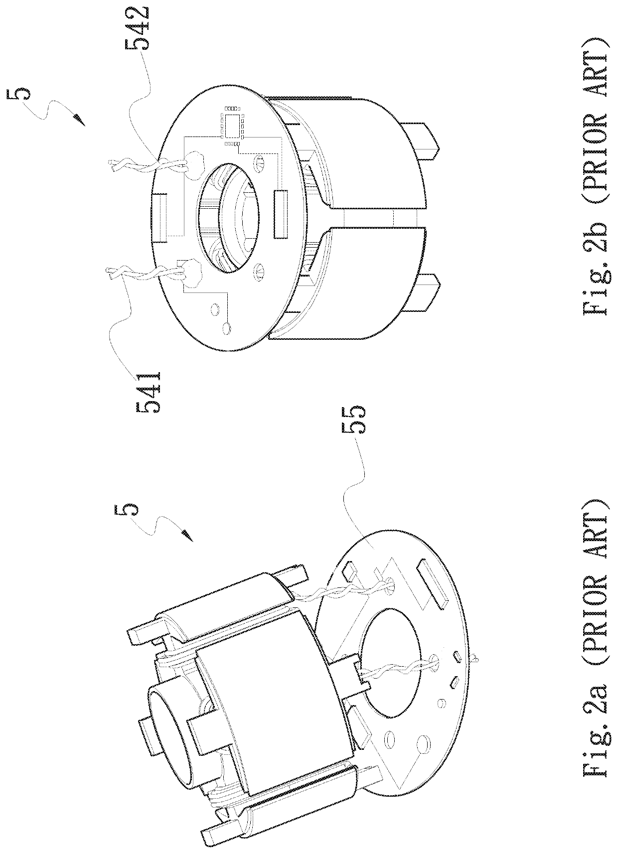
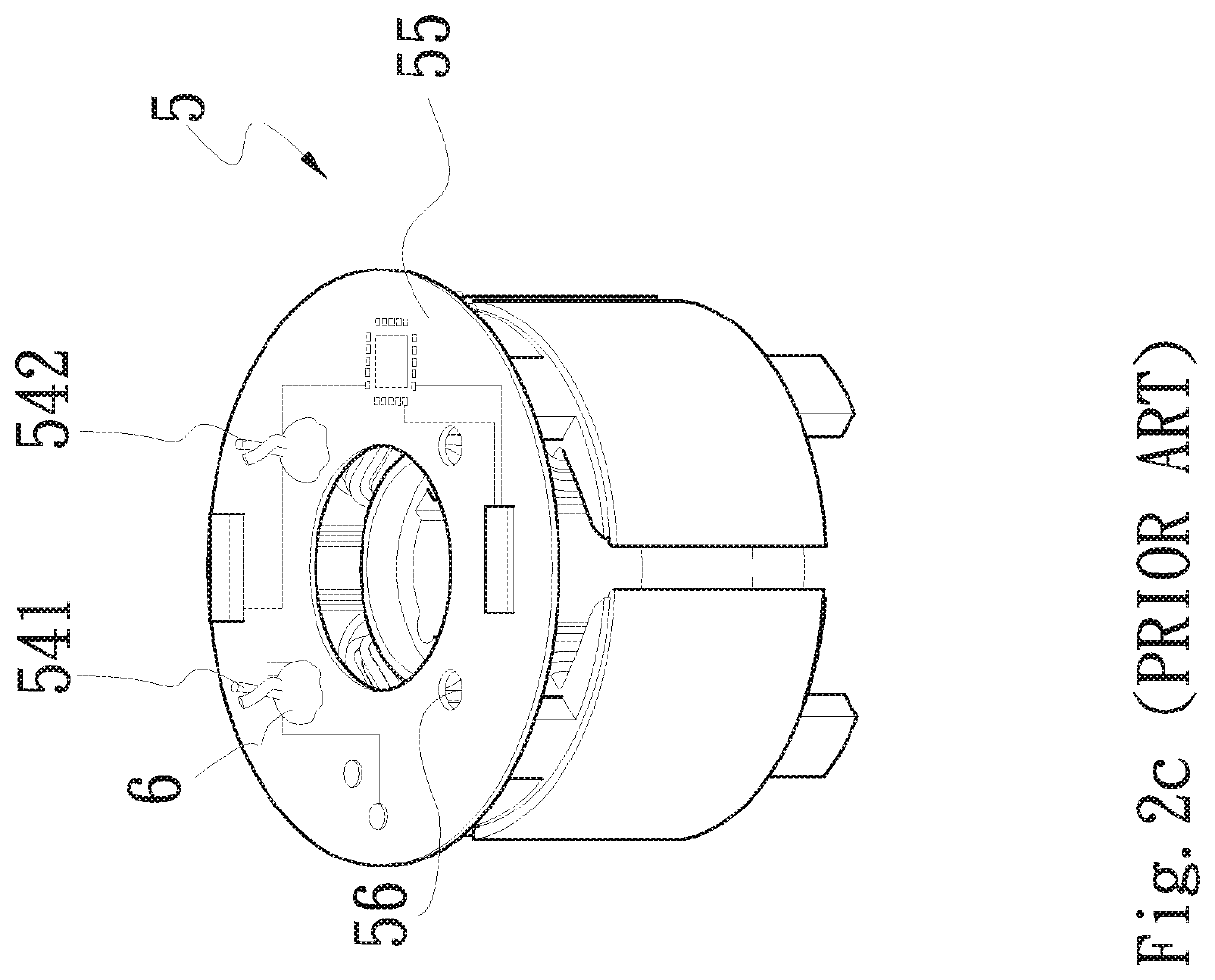
A problem of the expanded vias 56 is tin leaking and large weld nuggets 6.
Further, the remained sections of the front and back ends of the coils 54 tend to cause a short circuit if they are too long and therefore, must be manually cut off, which again consumes a lot of time and labors.
While the conventional fan stator coil winding operation can be done with a mechanically automated machine, the steps of twisting and trimming the front ends and back ends of the wound lead wires still rely on manual handling, which inevitably prevents the conventional fan stator manufacturing from high production efficiency and increased good yield rate.

Method used


Image

  • Manufacturing method of fan stator structure
  • Manufacturing method of fan stator structure
  • Manufacturing method of fan stator structure

Examples


Embodiment Construction

[0022]The present invention will now be described with some preferred embodiments thereof and by referring to the accompanying drawings. For the purpose of easy to understand, elements that are the same in the preferred embodiments are denoted by the same reference numerals.

[0023]Please refer to FIG. 3, which is a flowchart showing steps included in a manufacturing method of fan stator structure according to a first embodiment of the present invention; and to 4a, which is a perspective view of a fan stator structure manufactured using the method according to the first embodiment of the present invention; and to 4b, which shows a coil lead wire holder 2 used in the method of the present invention. As shown, the method according to the first embodiment of the present invention includes the following steps:

[0024]S1: Providing a fan stator;

[0025]S2: Providing a plurality of coil lead wire holders at an end of the fan stator; and

[0026]S3: Winding lead wires on the fan stator to form coil...


PUM


Abstract

A manufacturing method of fan stator structure includes the steps of providing a fan stator; providing a plurality of coil lead wire holders at an end of the fan stator; and winding lead wires on the fan stator to form coils, and setting and connecting a front end and a back end of each of the lead wires to the coil lead wire holders. The above method eliminates the drawbacks of the conventional fan stator coil winding operation, such as requiring manual twisting and trimming of the lead wire front ends and back ends and leaking of tin solder occurred during welding of the lead wires to a circuit board.

Description

FIELD OF THE INVENTION[0001]The present invention relates to a manufacturing method of fan stator structure, and more particularly, to a manufacturing method of fan stator structure, which enables increased efficiency in winding stator coils, trimming lead wires of the stator coils, and electrically connecting the coils to a circuit board.BACKGROUND OF THE INVENTION[0002]A stator assembly and a rotor assembly are two main components of a fan, and the stator assembly causes the rotor assembly to rotate through electromagnetic induction. As shown in FIGS. 1a, 1b and 2a to 2c, a conventional stator assembly 5 is formed by laminating a plurality of silicon steel sheets 51; providing upper and lower insulating supports 52, 53 to upper and lower ends of the silicon steel lamination 51, respectively; winding lead wires around poles of the silicon steel lamination to form coils 54; and finally, welding the coils to a circuit board 55 to complete the stator manufacturing procedures.[0003]Acc...

Claims


Application Information

Patent Timeline
Patent Type & Authority Applications(United States)
IPC IPC(8): H02K15/08H02K7/14H02K15/00H02K15/02
CPCH02K15/08H02K15/02H02K15/0081H02K7/14H02K2203/03H02K3/522H02K15/0068
Inventor LU, YEH-CHIHCHEN, HSIN-HUNG
Owner ASIA VITAL COMPONENTS (CHINA) CO LTD
Why Eureka
Try Eureka