
Driving method for electrooptical device, driving device for electrooptical device, electrooptical device and electronic device

a driving device and electrooptical technology, applied in the direction of instruments, static indicating devices, etc., can solve the problems of affecting long-term reliability, loss of dc balance, and inability so as to ensure long-term reliability and ensure long-term reliability of electronic devices.

Inactive Publication Date: 2014-09-18
SEIKO EPSON CORP
View PDF3 Cites 9 Cited by
  • Summary
  • Abstract
  • Description
  • Claims
  • Application Information

AI Technical Summary

Benefits of technology

This patent describes an electrophoretic display device that uses an active matrix driving method. However, the invention is not limited to this specific method. The device has a display and a control circuit that drives it. The control circuit has various components such as a display driver, a timing controller, and a power supply. The device uses a combination of these components to create a display that is easy to control and operate. The technical effects of this invention include improved display quality, reduced power consumption, and improved user experience.

Problems solved by technology

This gives rise to the problem that the amount of data of driving waveforms to be prestored in the lookup table becomes enormous.
However, a problem with the method disclosed in Hiji is that, when resetting the luminance, the balance of an integral value of voltages applied to electrophoretic particles with respect to a time period (DC balance) is lost.
Therefore, if the driving of pixels is repeated while the DC balance is lost, a problem arises in that long-term reliability is adversely affected.

Method used


Image

  • Driving method for electrooptical device, driving device for electrooptical device, electrooptical device and electronic device
  • Driving method for electrooptical device, driving device for electrooptical device, electrooptical device and electronic device
  • Driving method for electrooptical device, driving device for electrooptical device, electrooptical device and electronic device

Examples


first embodiment

1. First Embodiment

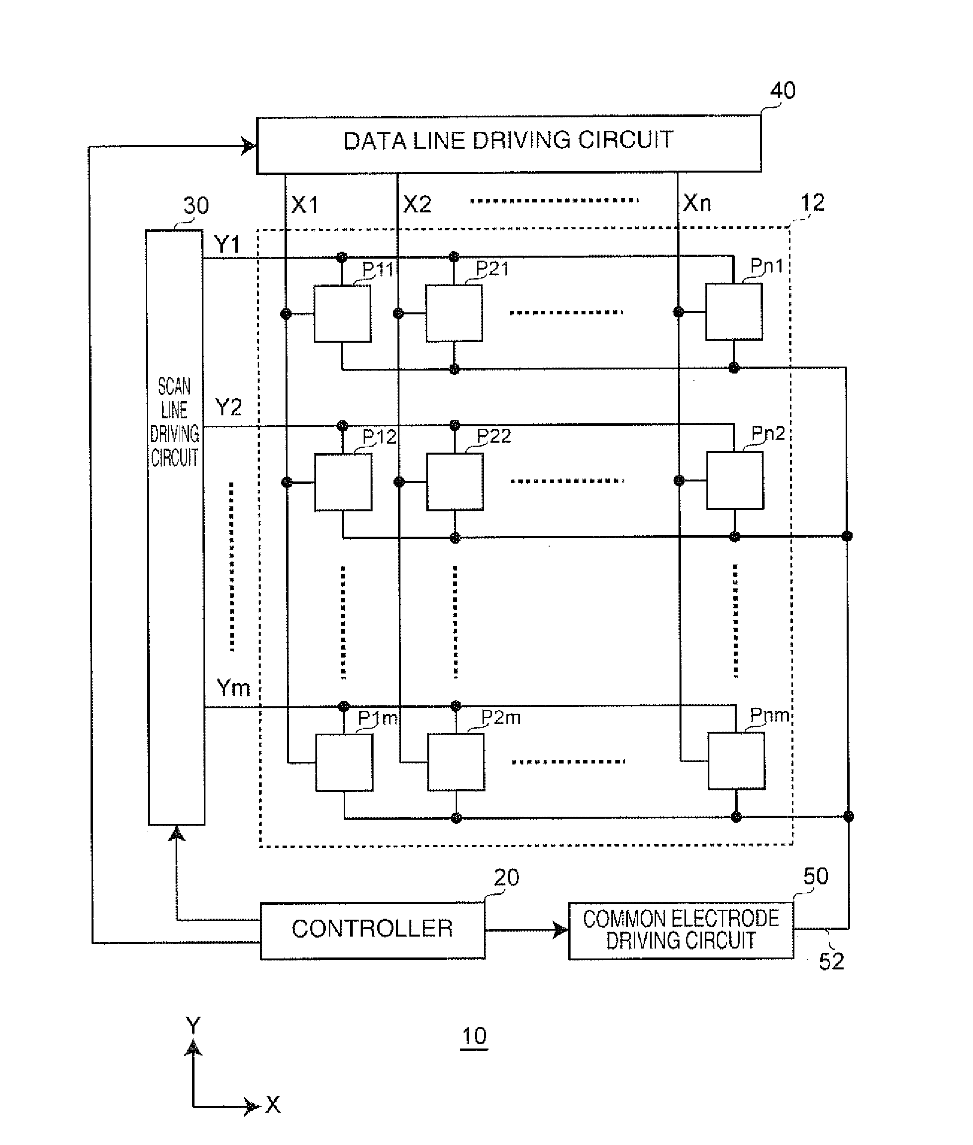
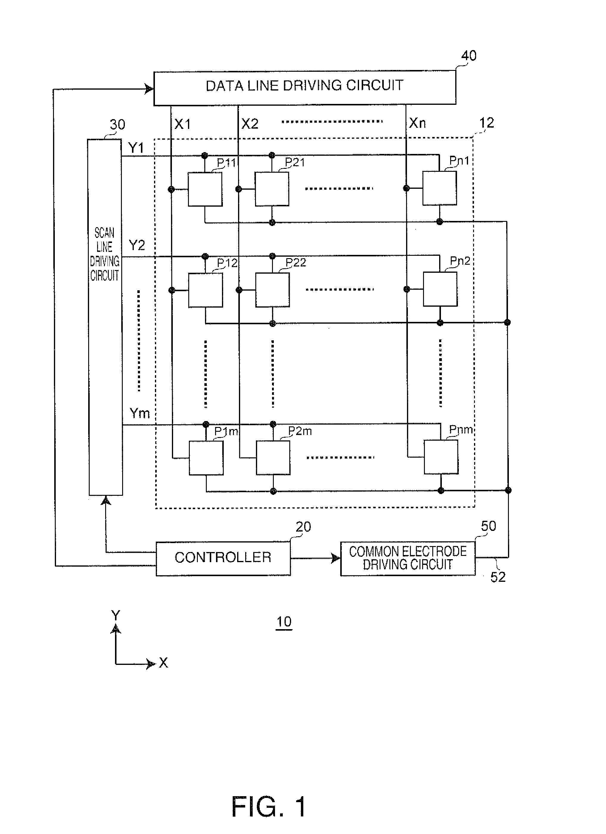
[0067]FIG. 1 is a block diagram showing an example of a configuration of an electrophoretic display device serving as an electrooptical device according to a first embodiment of the invention.

[0068]In an electrophoretic display device 10 according to the first embodiment, pixels include display elements that have a function of a memory. The property of the electrophoretic display device 10 is such that, when a display state is not updated, a previous display state is retained. The electrophoretic display device 10 includes a pixel region 12, a controller 20, a scan line driving circuit 30, a data line driving circuit 40, and a common electrode driving circuit 50. A part or all of the scan line driving circuit 30, the data line driving circuit 40, and the common electrode driving circuit 50 function as a driving device for the electrophoretic display device 10. The pixel region 12 in FIG. 1 may serve as an electrophoretic display device, with the controller 20, the...

second embodiment

2. Second Embodiment

[0108]The first embodiment has described the example in which the microcapsule 70 includes the solvent 72 and the electrophoretic particles 74 and 76, and control is performed using two types of driving voltages. However, embodiments of the invention are not limited in this way. In a second embodiment, a microcapsule includes a solvent and a plurality of electrophoretic particles with different thresholds, and control is performed using four types of driving voltages. For the sake of explanation, the following describes portions of the second embodiment that are different from the first embodiment.

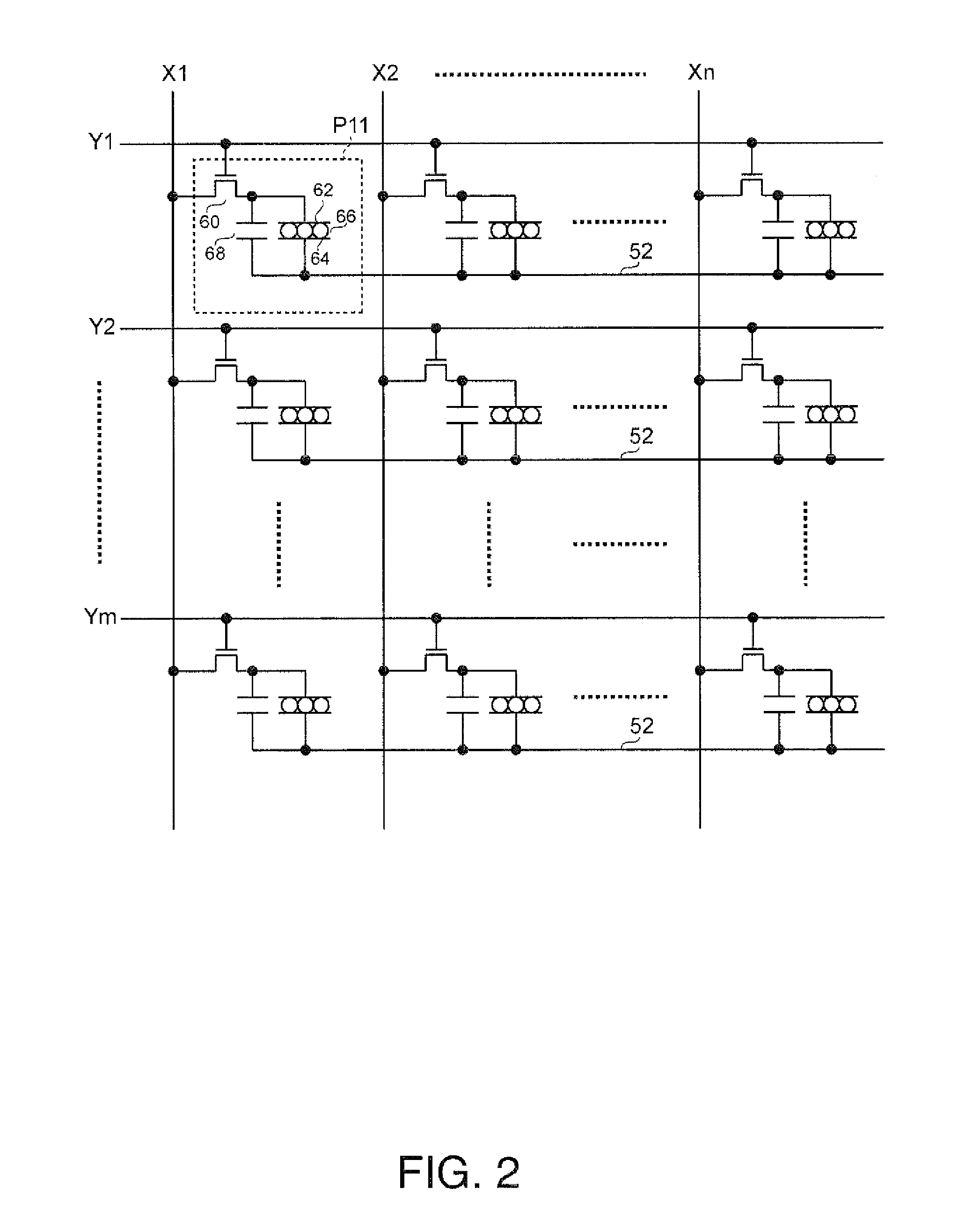
[0109]FIG. 9 shows a general configuration of a microcapsule composing the electrophoretic elements according to the second embodiment. In the second embodiment, the electrophoretic elements 66 of FIG. 2 are composed of a microcapsule 170 shown in FIG. 9.

[0110]The microcapsule 170 according to the second embodiment includes an unpigmented viscous solvent 172, a pluralit...

third embodiment

3. Third Embodiment

[0130]Embodiments of the invention are not limited to the first or second embodiment. In a third embodiment, a microcapsule includes a solvent and a plurality of electrophoretic particles with different thresholds, and control is performed using eight types of driving voltages. For the sake of explanation, the following describes portions of the third embodiment that are different from the first embodiment.

[0131]FIG. 16 shows a general configuration of a microcapsule composing the electrophoretic elements according to the third embodiment. In the third embodiment, the electrophoretic elements 66 of FIG. 2 are composed of a microcapsule 270 shown in FIG. 16.

[0132]The microcapsule 270 according to the third embodiment includes a viscous solvent 272 pigmented in black, a plurality of electrophoretic particles 274 pigmented in red, a plurality of electrophoretic particles 276 pigmented in green, and a plurality of electrophoretic particles 278 pigmented in blue. The e...


PUM


Abstract

A driving method for an electrophoretic display device composed of a pixel electrode, an opposing electrode, and electrophoretic elements includes a color setting step and a DC resetting step. The electrophoretic elements are disposed between the pixel electrode and the opposing electrode and include a plurality of electrophoretic particles. In the color setting step, the plurality of electrophoretic particles are set in a first state by applying one or more types of driving voltages between the pixel electrode and the opposing electrode. In the DC resetting step, driving voltages for resetting an integral value of the driving voltages with respect to a driving time period in the color setting step are applied between the pixel electrode and the opposing electrode.

Description

CROSS-REFERENCE TO RELATED APPLICATIONS[0001]This application claims priority to Japanese Patent Application No. 2013-050106 filed on Mar. 13, 2013. The entire disclosure of Japanese Patent Application No. 2013-050106 is hereby incorporated herein by reference.BACKGROUND[0002]1. Technical Field[0003]The present invention relates to a driving method for an electrooptical device, a driving device for an electrooptical device, an electrooptical device, an electronic device, and the like.[0004]2. Related Art[0005]An electrophoretic display device is known as one example of an electrooptical device. An electrophoretic display device is configured such that electrophoretic elements including pigmented electrophoretic particles are held between a pixel electrode and an opposing electrode. The electrophoretic display device displays an image by causing the electrophoretic particles to migrate through application of a voltage between these two electrodes. At this time, in the electrophoretic...

Claims


Application Information

Patent Timeline
Patent Type & Authority Applications(United States)
IPC IPC(8): G09G3/34
CPCG09G3/344G09G3/2003G09G2310/061G09G2310/065G09G2310/068G09G2320/0204
Inventor OGAWA, HIDEKIFUJIMORI, KEITARO
Owner SEIKO EPSON CORP
Learn More