Stereoscopic microscope

a stereoscopic microscope and microscope technology, applied in the field of stereoscopic instruments, can solve the problems of not being able to call stereoscopic microscopes, not being able to accurately measure the distance of one point in three, and the true depth perception, so as to reduce the separation of the pupils of the user, increase the second angular relationship, and reduce the effect of the separation of the pupils

Inactive Publication Date: 2014-09-18
WARD JOHN
View PDF4 Cites 16 Cited by
  • Summary
  • Abstract
  • Description
  • Claims
  • Application Information

AI Technical Summary

Benefits of technology

[0032]By providing a second angle adjustment that enables a separation between the left and right exit pupils to decrease as the angle defining the second angular relationship increases, adjustment of the second angular relationship can be made in a manner requiring little or no additional input from the user, beyond that of making the adjustment itself.
[0033]In some embodiments, the second angle adjustment means comprises a beam steering means in each of the left and right optical paths, each of the beam steering means being arranged to rotate about an axis coincident with a central optical axis of the respective incoming left and right optical beams, and to deflect the respective outgoing left and right optical beams by an angle of inclination which is fixed relative to its respective left or right axis of rotation, the left and right inclined outgoing optical beams subtending between them an angle which varies with the deg...

Problems solved by technology

However, this type of microscope cannot be called ‘stereoscopic’ since the images presented to each of the eyes of the user are identical.
However, true depth perception, the sense of how far away one point in three-dimensional space is relative to all others, can only be achieved by the brain by uti...

Method used


Image

  • Stereoscopic microscope
  • Stereoscopic microscope
  • Stereoscopic microscope

Examples


Embodiment Construction

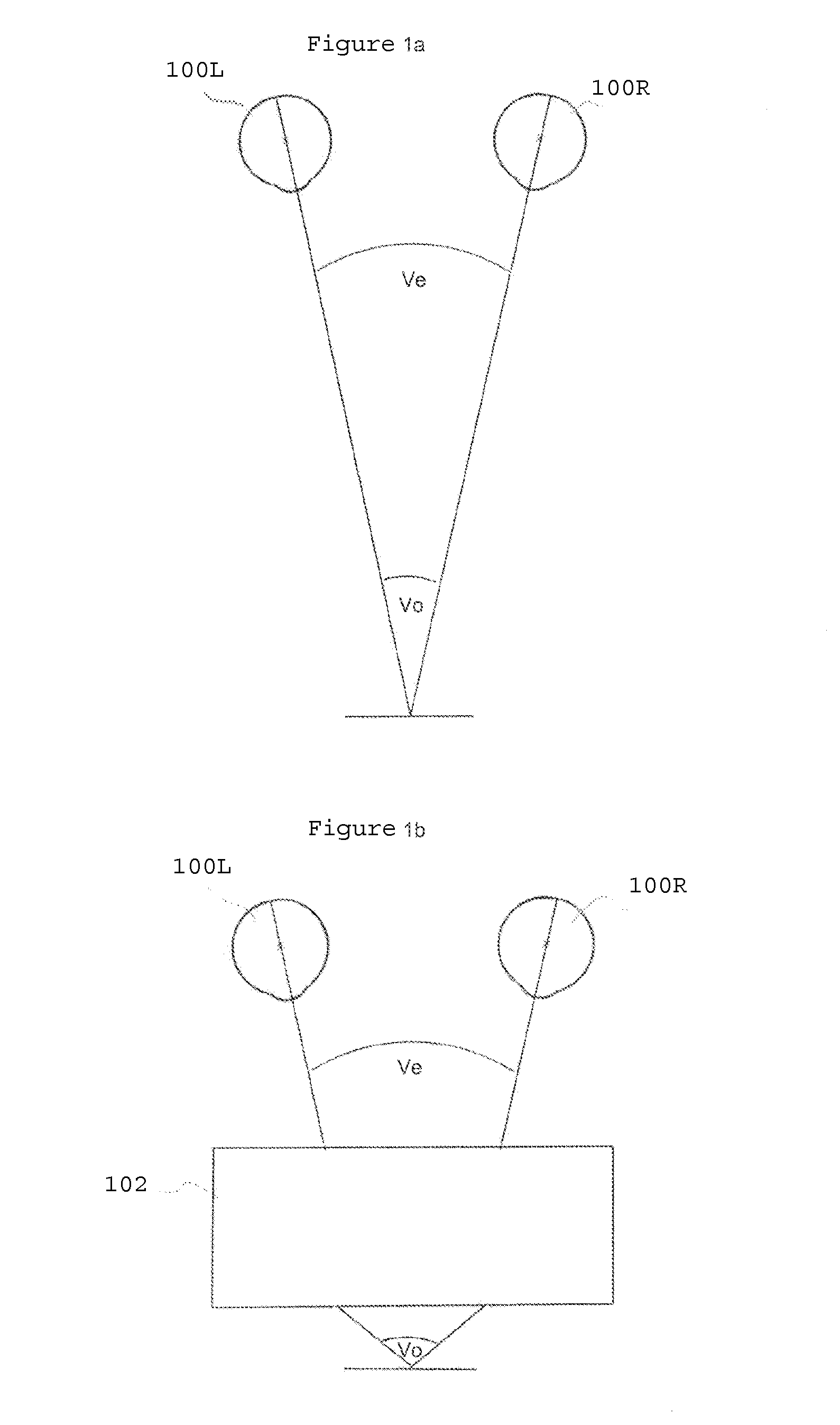
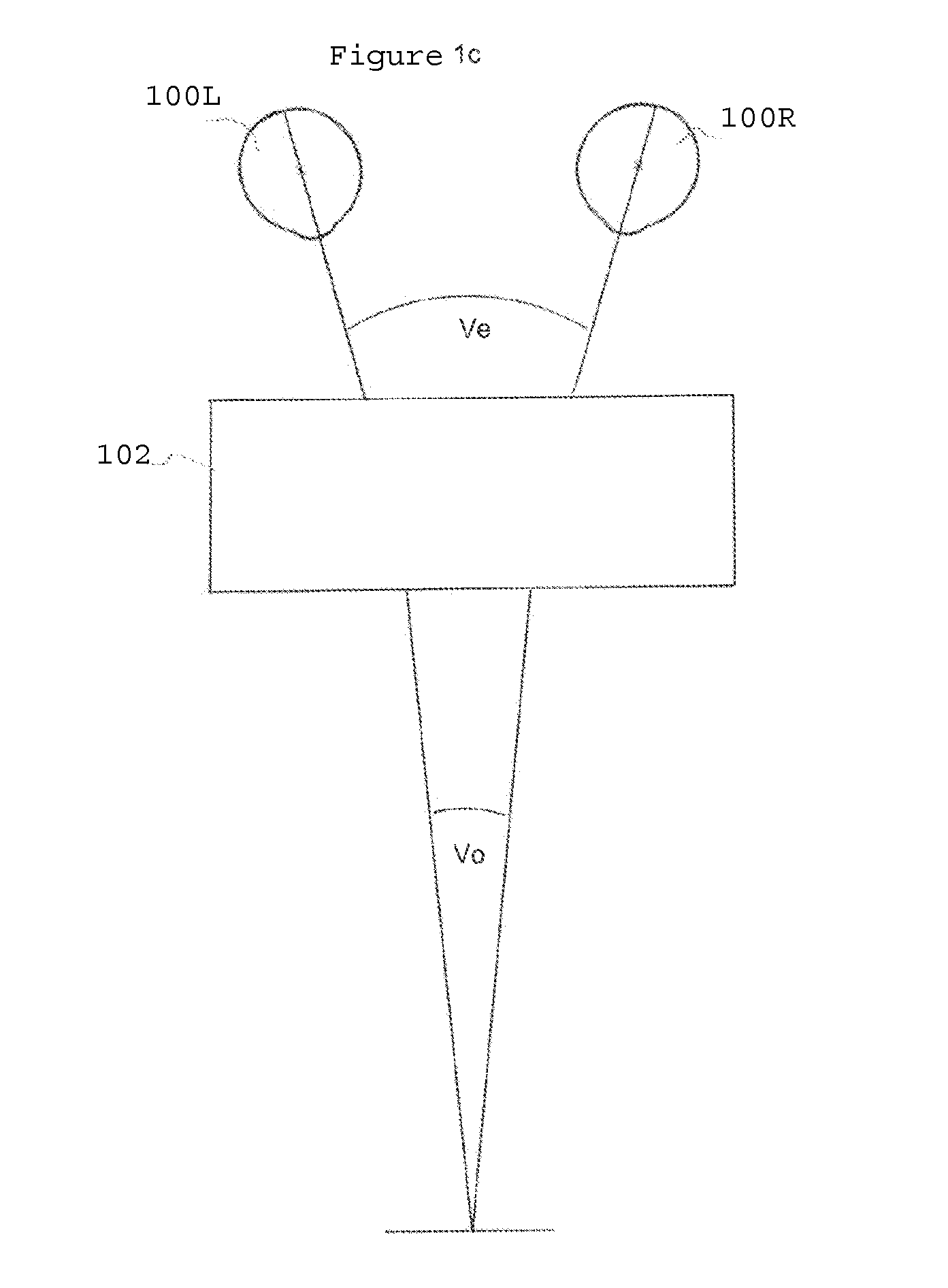
[0091]In unaided binocular vision, stereopsis is enabled, in part, by the difference in viewpoints of the left and right eyes; so-called binocular disparity. Because of the spatial separation of a person's eyes, the viewpoints of the two eyes converge on an object being viewed. Typically, the angle of convergence is small, with an upper limit of comfort of about 15°. The viewpoints of a pair of eyes 100L, 100R during unaided vision are shown in FIG. 1a. To achieve orthostereoscopic perception (objects appearing correctly proportioned in three dimensions) the angle of convergence included by the optical axes of an observers left and right eyes 100L, 100R, hereinafter referred to as eye-space vergence, ∠Ve, must equal the angle made by the left and right optical rays diverging from a point on an object, hereinafter referred to as the object-space vergence, ∠Vo. This condition is referred to herein as the “orthostereoscopic condition”. As shown in FIG. 1a, in unaided binocular vision t...


PUM


Abstract

Stereoscopic instruments for viewing stereoscopic images of objects at a range of magnifications are described. The stereoscopic instruments are arranged to provide an optical beam comprising light received from an object over a given angular range, and to split the optical beam into left and right optical beams each traversing a respective optical path. The left and right optical paths each transmit a sub-beam over a respective angular range, the respective angular ranges thereby defining a first angular relationship between the respective sub-beams. Each optical path comprises a first angle adjustment means for adjusting the first angular relationship. Some embodiments also include a means for transmitting images formed from the left and right sub-beams, the images having a second angular relationship related to a vergence angle at which a user's eyes view the object. By controlling the relative angles defined by first and second angular relationships, a degree of stereoscopy with which the user can view the object can be varied.

Description

CROSS-REFERENCE TO RELATED APPLICATIONS[0001]This application is a continuation under 35 U.S.C. §120 of International Application No. PCT / EP2012 / 073913, filed Nov. 29, 2012 (published by the International Bureau as International Publication No. WO / 2013 / 079571 on Jun. 6, 2013 in the English language), which claims priority to United Kingdom Patent Application No. 1120553.1, filed Nov. 29, 2011. Each of the above referenced patent applications is hereby incorporated by reference in its entirety.BACKGROUND OF THE INVENTION[0002]The present invention relates to a stereoscopic instrument and, in particular, but not exclusively, a stereoscopic microscope for providing three-dimensional perception of objects at high magnification powers.[0003]Binocular microscopes are commonly used in a wide range of scientific and industrial fields for inspecting samples with microscopic features. Typically, the principle of operation of the most widely used microscopes is to split a single beam, formed b...

Claims


Application Information

Patent Timeline
IPC IPC(8): G02B21/22G02B21/36
CPCG02B21/22G02B21/361G02B21/24G02B30/34
Inventor WARD, JOHN
Owner WARD JOHN
Why Eureka
Try Eureka