Sector-Scanning Device

a sonar imaging and scanning device technology, applied in measurement devices, using reradiation, instruments, etc., can solve the problems of difficult reading, large footprint of the bottom of a given body of water, lack of detail in sonar images, etc., and achieve the effect of easy deployment and retracting

Active Publication Date: 2014-09-18
JOHNSON OUTDOORS
View PDF11 Cites 32 Cited by
  • Summary
  • Abstract
  • Description
  • Claims
  • Application Information

AI Technical Summary

Benefits of technology

[0012]In another aspect, embodiments of the invention provide a sonar imaging system configured to attach to a propeller pod of a trolling motor. Directly attaching to the propeller pod of a trolling motor allows for the user to easily deploy and retract the sonar imaging system in a manner they are already familiar with. The sonar imaging system is also oriented along the axis of the trolling motor propeller pod, allowing the user to aim the self-reciprocating sonar imaging device using the same foot pedal or electric control used to steer the trolling motor without requiring motion of the trolling motor itself to generate the images.

Problems solved by technology

Such systems tend to provide a large “footprint” of the bottom of a given body of water.
This large footprint results in sonar images that lack detail and may be difficult to read, especially for inexperienced users.

Method used


Image

  • Sector-Scanning Device
  • Sector-Scanning Device
  • Sector-Scanning Device

Examples


Embodiment Construction

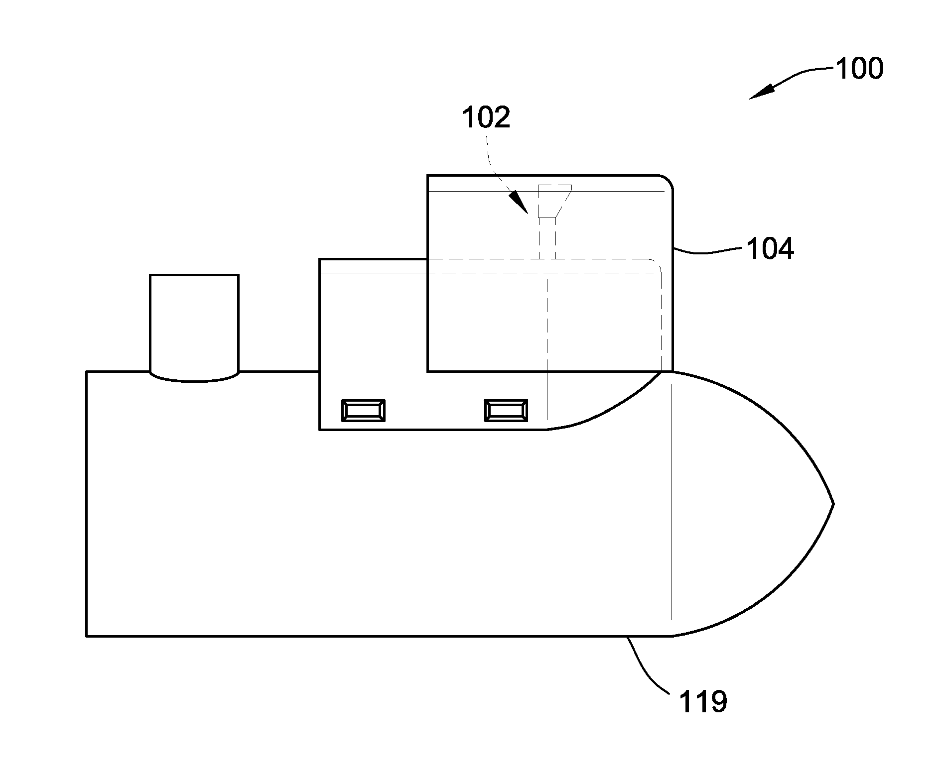
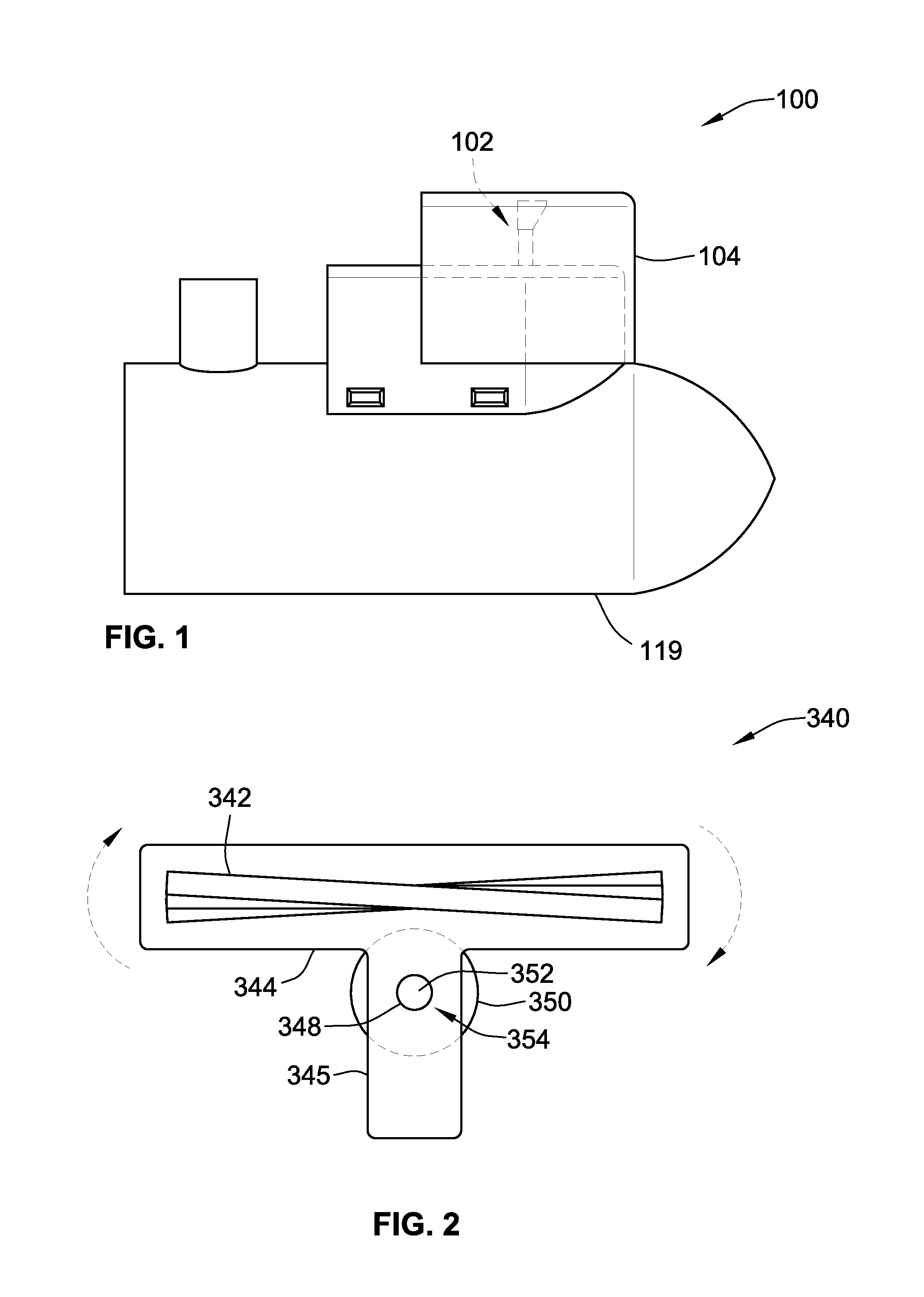
[0027]In this application, several embodiments of a sector-scanning sonar imaging system will be discussed. It should be noted, however, that while a number of embodiments will be illustrated and / or discussed hereinbelow, such embodiments should be taken by way of example and not by way of limitation. In these exemplary embodiments, the sector-scanning sonar imaging system may connect directly to a control head with display via the transducer connection and a control communications port, although other embodiments may communicate using other technology, e.g. Ethernet, Wi-Fi, Bluetooth, etc.

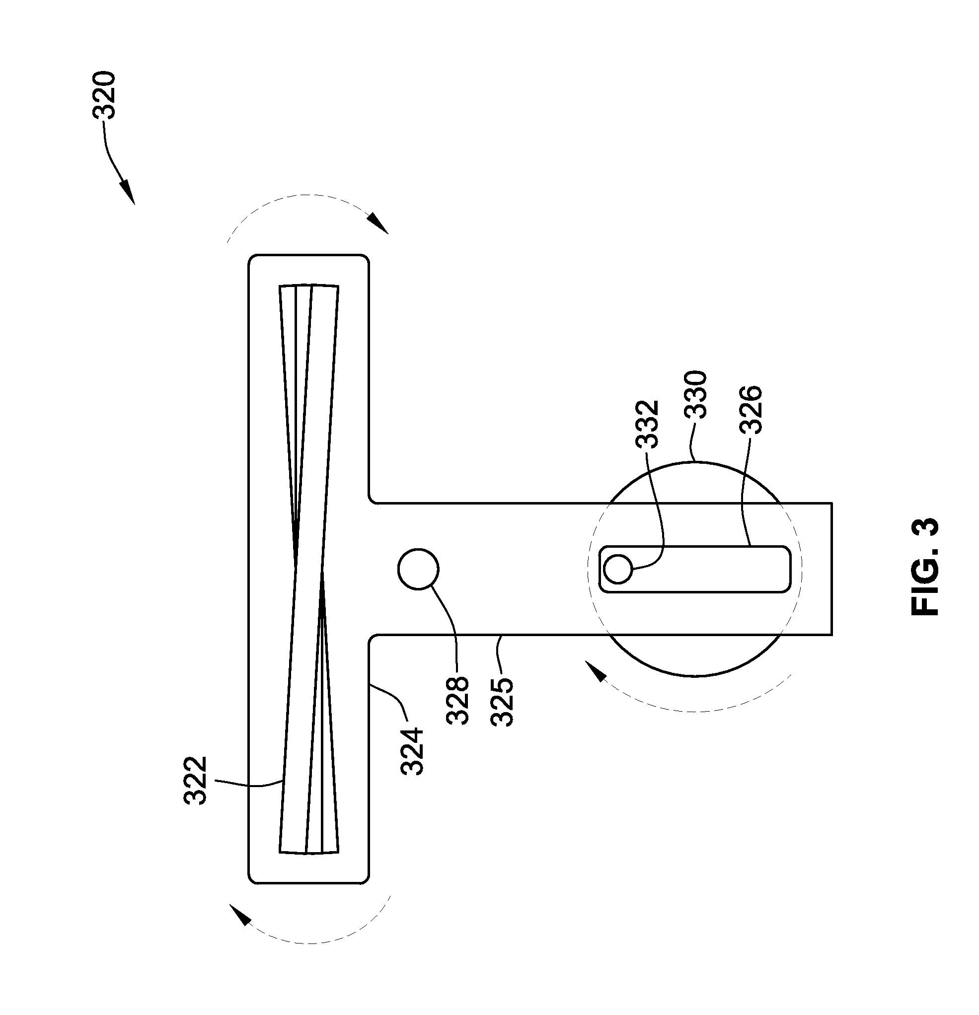
[0028]The sector scan sonar imaging system may be assembled in such a way to allow the removal of the sonar imaging transducer housing by the user. This allows the user to replace the transducer housing with one of a different design, allowing for different beam shapes, frequency optimization, or to replace a damaged transducer with a new one. In particular embodiments, when the sector-scanning so...


PUM


Abstract

A sector-scanning sonar imaging system with at least one sonar imaging element housed within a transducer housing coupled to a self-reciprocating mechanism, and a drive mechanism housed within a waterproof housing. The oscillating motion of the transducer housing produces a highly-detailed, photo like sector scan sonar image of the bottom and other objects surrounding the boat on which it is mounted. The drive mechanism housing may be rigidly attached to either a boat hull or to a trolling motor. The sonar imaging element housing may be removably attached to the drive mechanism, and shielded by an acoustically transparent shroud to protect the elements from damage. The sector-scanning sonar imaging system connects to a control head with display either directly, or through some other communications protocol, such as a wireless protocol.

Description

CROSS-REFERENCE TO RELATED PATENT APPLICATIONS[0001]This patent application claims the benefit of U.S. Provisional Patent Application No. 61 / 794,502, filed Mar. 15, 2013, the entire teachings and disclosure of which are incorporated herein by reference thereto.FIELD OF THE INVENTION[0002]The present invention relates generally to sonar imaging systems for use in sport fishing applications such as in a fish finder, sonar depth sounder, etc., and more particularly to a sector-scanning sonar imaging systems for imaging of the underwater environment all around the watercraft rather than just below or to the sides of the watercraft.BACKGROUND OF THE INVENTION[0003]Sonar devices that transmit sound waves have been used previously to obtain information about underwater articles, including fish, structures and obstructions, and the bottom. The sound waves travel from a transducer mounted to a bottom surface of the vessel through the water. The sound wave transmits from the sonar devices in ...

Claims


Application Information

Patent Timeline
Patent Type & Authority Applications(United States)
IPC IPC(8): G01S15/89G01S7/56
CPCG01S7/56G01S15/89G01S7/003G01S7/521G01S7/6236G01S15/42G01S15/86G01S15/87G01S15/96
Inventor BETTS, DAVID A.DEHART, SEAN M.
Owner JOHNSON OUTDOORS
Why Eureka
Try Eureka