Pipe assembly and flow assurance system

a technology of flow assurance and pipe assembly, which is applied in the direction of service pipe systems, pipe heating/cooling, and borehole/well accessories, etc., can solve the problems of incomplete blockage of the pipeline, reduced pipeline cross-section, and low detail of the structure and layout of the document of hoffmann et al., so as to reduce the risk of water entering the tunnel and ensure the seal

Inactive Publication Date: 2014-09-18
VETCO GRAY SCANDINAVIA
View PDF21 Cites 4 Cited by
  • Summary
  • Abstract
  • Description
  • Claims
  • Application Information

AI Technical Summary

Benefits of technology

[0018]In an embodiment, the tunnel walls are designed to be cup-shaped in a sectional view. In addition, the ends or edges of the tunnel walls that face the inner pipe may be formed with a radius corresponding substantially to the outer radius of the inner pipe. These measures advantageously provide more efficient seal between the tunnel and the annular space, reducing the risk of penetration of water into the tunnel.

Problems solved by technology

The deposits may grow rapidly to cause a reduction of the pipeline cross-section, and may ultimately result in a complete blockage of the pipeline if countermeasures are not applied.
However, the Hoffmann et al document is not very detailed in its description of the structure and layout of the heated pipe-in-pipe pipeline that is utilized in the cooling and heating process.
However, although Bursaux is detailed with respect to the structural buildup of the pipe-in-pipe flow system, the document lacks guidance regarding installation of electrical heating facilities in the pipe-in-pipe structure.

Method used


Image

  • Pipe assembly and flow assurance system
  • Pipe assembly and flow assurance system
  • Pipe assembly and flow assurance system

Examples


Embodiment Construction

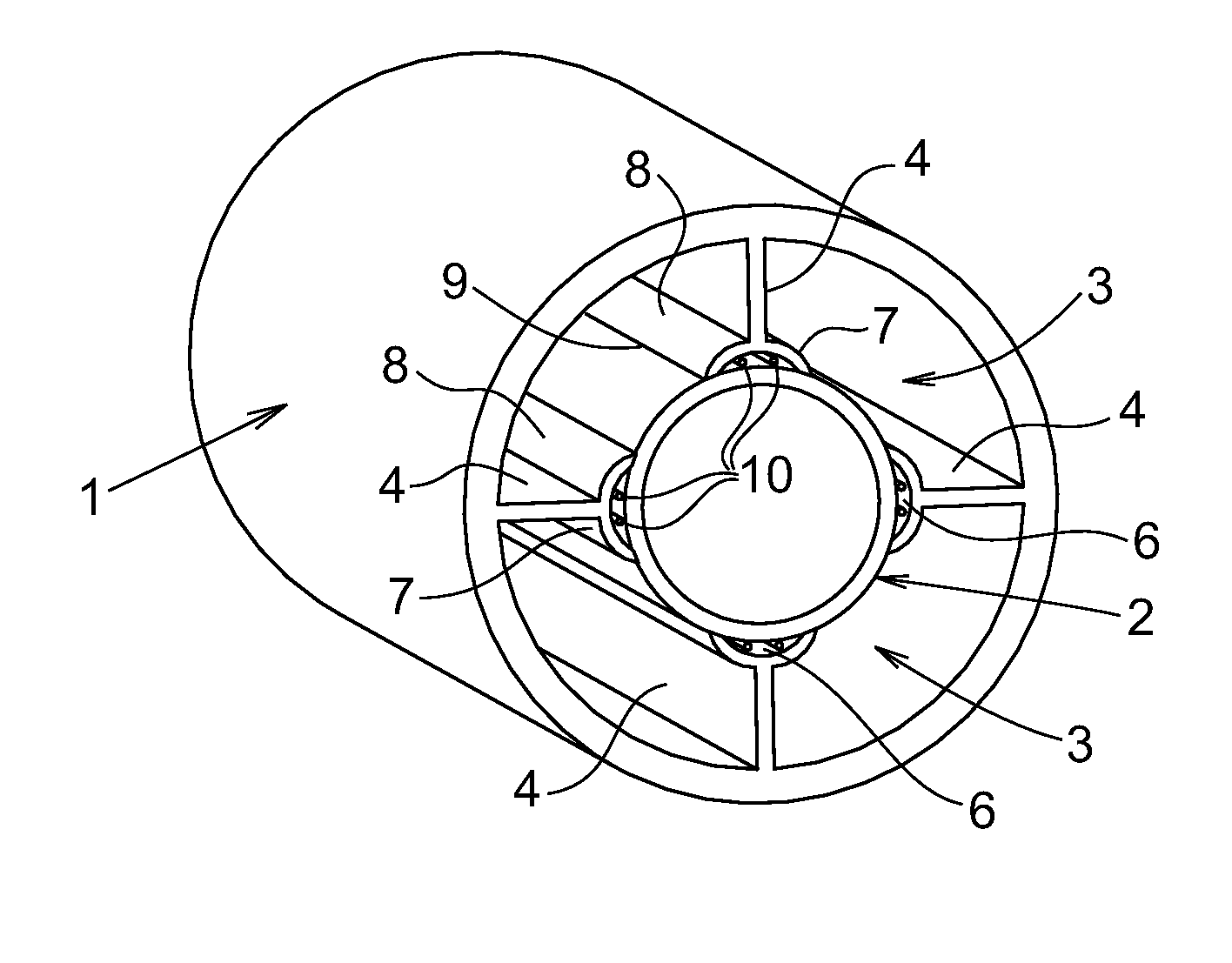
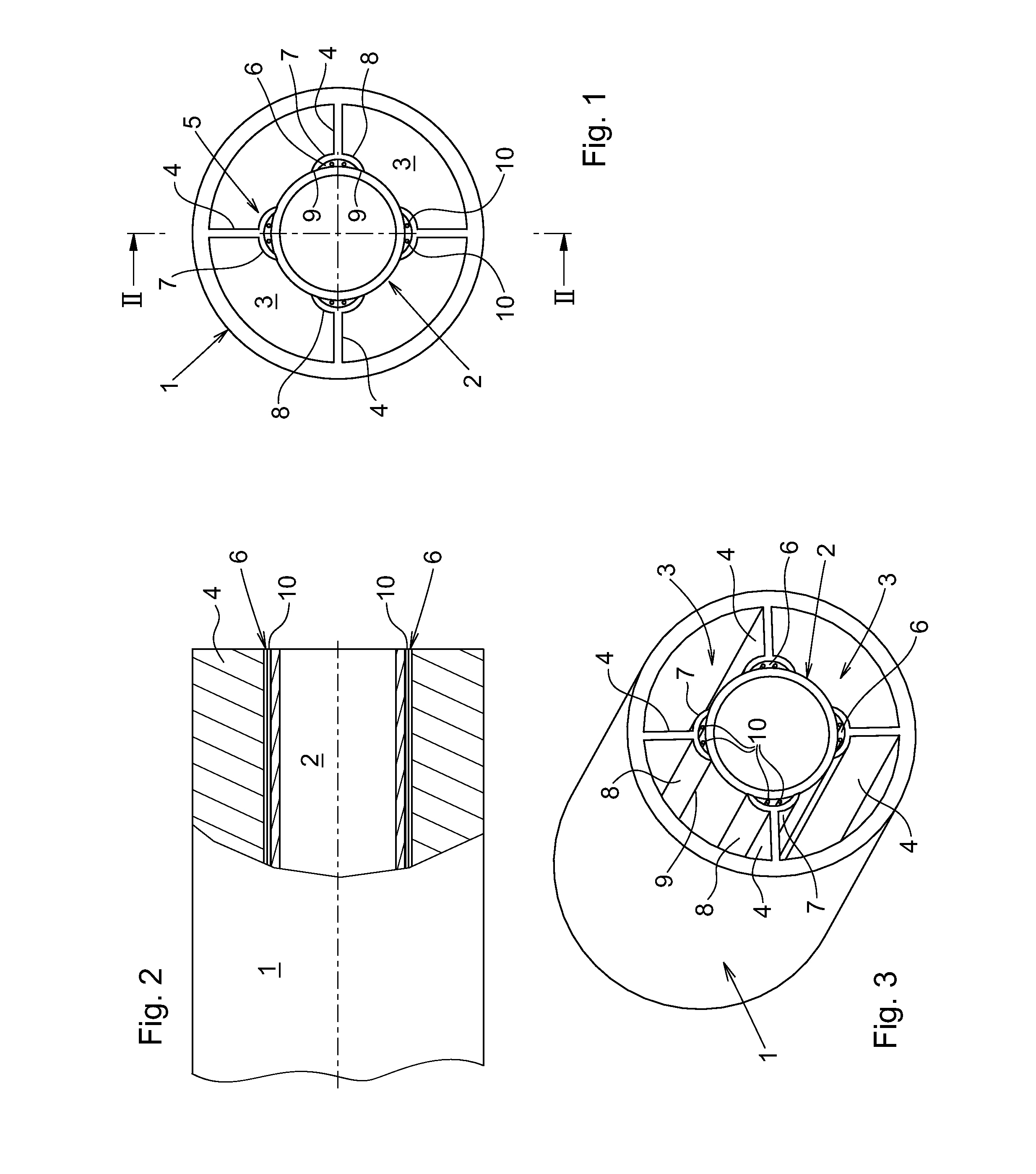
[0026]With reference to the drawings, the pipe assembly comprises an outer pipe 1 in surrounding relation about an inner pipe 2, forming between them an annular volume 3. The inner pipe 2 is suspended in the ends of legs 4 which reach towards the inner pipe from the inner periphery or inside of the outer pipe 1. The legs 4 extend uninterrupted in the longitudinal direction of the outer and inner pipes, the legs forming partition walls which divide the annular volume 3 into parallel sections. The embodiment illustrated in FIGS. 1-3 has four legs 4 which are equally distributed about the inner pipe, the legs dividing the annular volume 3 into four sections having the same sectional area.

[0027]Naturally, the number of legs can be varied and the illustrated embodiment disclosing four equally distributed legs is merely exemplifying, in terms of stability and mutual alignment between the outer and inner pipes, and in terms of production and material costs as well.

[0028]Each leg 4 comprise...


PUM


Abstract

A pipe assembly comprising an outer pipe in surrounding relation about an inner pipe, wherein the inner pipe is suspended in free inner ends of legs extended in an annular space that is formed between the outer and inner pipes, the legs reaching radially towards the inner pipe from an inner periphery of the outer pipe. At least one of the legs carries in its inner end a support foot that is formed with a recess facing towards the inner pipe. The recess forms a tunnel that is defined through an outer periphery of the inner pipe and opposite tunnel walls that reach from the leg to the inner pipe.

Description

BACKGROUND OF THE INVENTION[0001]The present invention refers to a pipe-in-pipe assembly that is adapted for transport of fluids. The pipe assembly is specifically useful in a system for long distance transport of hydrocarbon fluid produced in a subsea hydrocarbon production setup, wherein the system comprises flow assurance through wax and hydrate control by cooling and heating. In accordance herewith, the present invention refers also to a flow assurance system comprising the pipe assembly of the present invention.[0002]Long distance transport of hydrocarbons through a pipeline in seawater from a subsea well to a surface or land-based production facility usually involves the task of controlling and removing deposits of wax / paraffin that is dissolved in the hot fluid and precipitate on the inner wall of the pipeline which is cooled by the surrounding sea. The deposits may grow rapidly to cause a reduction of the pipeline cross-section, and may ultimately result in a complete blocka...

Claims


Application Information

Patent Timeline
Patent Type & Authority Applications(United States)
IPC IPC(8): F16L53/00F16L9/14F16L53/38F16L53/70
CPCF16L53/004F16L9/14F16L53/008F16L7/02E21B43/01F16L9/19F16L55/24F16L53/38F16L53/70
Inventor ROSVOLD, ODD MARIUS
Owner VETCO GRAY SCANDINAVIA
Why Eureka
Try Eureka