Fixing device, image forming apparatus, and fixing method

a technology of fixing device and fixing rotary body, which is applied in the direction of electrographic process apparatus, instruments, optics, etc., can solve the problems of uneven heating uneven temperature and non-conveyance span situated at each lateral end of the fixing rotary body

Active Publication Date: 2014-09-18
RICOH KK
View PDF12 Cites 28 Cited by
  • Summary
  • Abstract
  • Description
  • Claims
  • Application Information

AI Technical Summary

Problems solved by technology

Accordingly, after a plurality of recording media is conveyed through the fixing nip continuously, a non-conveyance span situated at each lateral end of the fixing rotary body may overheat.
Accordingly, the heater may heat the fixing rotary body unevenly.
Even after the fixing rotary body rotates idly for a while, unevenness of temperature of the fixing rotary body may not be eliminated.
Thus, even after the fixing rotary body rotates idly for an extended period of time, unevenness of temperature of the fixing rotary body may not be eliminated.
Uneven temperature of the fixing rotary body may thermally expand the fixing rotary body locally, causing warping and deformation on the surface of the fixing rotary body which may obstruct formation of the fixing nip between the fixing rotary body and the opposed body.
Accordingly, the fixing rotary body and the opposed body may not apply heat and pressure to the recording medium conveyed through the fixing nip properly.
For example, if the fixing device incorporates the heat shield that shields the fixing rotary body from the heater in the non-conveyance span of the fixing rotary body where the recording medium is not conveyed, the heat shield may develop unevenness of the temperature of the fixing rotary body with an increased temperature difference, warping the fixing rotary body substantially.

Method used


Image

  • Fixing device, image forming apparatus, and fixing method
  • Fixing device, image forming apparatus, and fixing method
  • Fixing device, image forming apparatus, and fixing method

Examples


Embodiment Construction

[0039]In describing exemplary embodiments illustrated in the drawings, specific terminology is employed for the sake of clarity. However, the disclosure of this specification is not intended to be limited to the specific terminology so selected and it is to be understood that each specific element includes all technical equivalents that operate in a similar manner and achieve a similar result.

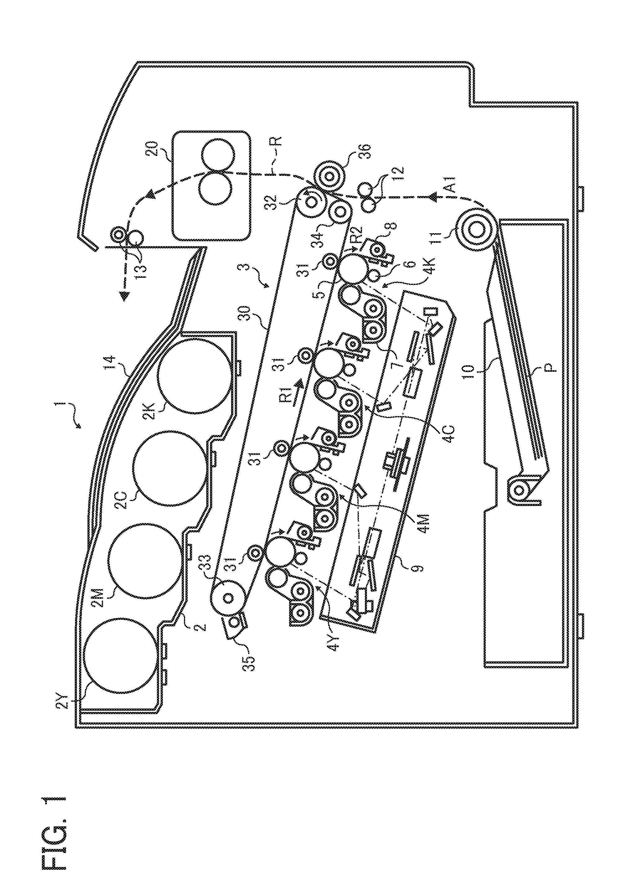
[0040]Referring now to the drawings, wherein like reference numerals designate identical or corresponding parts throughout the several views, in particular to FIG. 1, an image forming apparatus 1 according to an exemplary embodiment of the present invention is explained.

[0041]FIG. 1 is a schematic vertical sectional view of the image forming apparatus 1. The image forming apparatus 1 may be a copier, a facsimile machine, a printer, a multifunction peripheral or a multifunction printer (MFP) having at least one of copying, printing, scanning, facsimile, and plotter functions, or the like. Accord...


PUM


Abstract

A fixing device includes a fixing rotary body and a heater for heating the fixing rotary body. An opposed body contacts the fixing rotary body with releasable pressure therebetween to form a fixing nip therebetween through which a recording medium is conveyed. A heat shield is interposed between the heater and the fixing rotary body and movable in a circumferential direction of the fixing rotary body to shield the fixing rotary body from the heater in a variable circumferential direct heating span of the fixing rotary body where the heater is disposed opposite the fixing rotary body directly. A controller is operatively connected to the heater and the heat shield to move the heat shield after the controller turns on the heater as a print job starts so as to change an area of the direct heating span of the fixing rotary body.

Description

CROSS-REFERENCE TO RELATED APPLICATION[0001]This patent application is based on and claims priority pursuant to 35 U.S.C. §119 to Japanese Patent Application No. 2013-053781, filed on Mar. 15, 2013, in the Japanese Patent Office, the entire disclosure of which is hereby incorporated by reference herein.BACKGROUND[0002]1. Technical Field[0003]Exemplary aspects of the present invention relate to a fixing device, an image forming apparatus, and a fixing method, and more particularly, to a fixing device for fixing a toner image on a recording medium, an image forming apparatus incorporating the fixing device, and a fixing method for fixing a toner image on a recording medium.[0004]2. Description of the Background[0005]Related-art image forming apparatuses, such as copiers, facsimile machines, printers, or multifunction printers having two or more of copying, printing, scanning, facsimile, plotter, and other functions, typically form an image on a recording medium according to image data...

Claims


Application Information

Patent Timeline
Patent Type & Authority Applications(United States)
IPC IPC(8): G03G15/20
CPCG03G15/2032G03G15/2017G03G15/2039G03G15/2042G03G2215/2035
Inventor YUASA, SHUUTAROHTAMAKI, SHUNTAROSEKI, TAKAYUKIYOSHINAGA, HIROSHIARAI, YUJIMIMBU, RYUUICHIYAMAGUCHI, YOSHIKISHIMOKAWA, TOSHIHIKOIKEBUCHI, YUTAKASAITO, KAZUYA
Owner RICOH KK
Why Eureka
Try Eureka