Bi-Directional Overrunning Clutch With Improved Indexing Mechanism

a bi-directional overrunning and indexing technology, applied in the field of clutches, can solve the problems of cumbersome vehicles, vehicle stopping, and more expensive limited slip differentials, and achieve the effects of improving the indexing mechanism, and improving the indexing

Active Publication Date: 2014-09-18
HILLIARD CORP
View PDF4 Cites 15 Cited by
  • Summary
  • Abstract
  • Description
  • Claims
  • Application Information

AI Technical Summary

Benefits of technology

[0021]The foregoing and other features of the invention and advantages of the present invention will become more apparent in light of the following detailed description of the preferred embodiments, as illustrated in the accompanying figures. As will be realized, the invention is capable of modifications in various respects, all without departing from the invention. Accordingly, the drawings and the description are to be regarded as illustrative in nature, and not as restrictive.

Problems solved by technology

Prior four-wheel drive and all terrain vehicles were cumbersome since they required the operator to manually engage and disengage the secondary drive shaft, e.g., by stopping the vehicle to physically lock / unlock the wheel hubs.
An open differential allows differential action between the half shafts but, when one wheel loses traction, all available torque is transferred to the wheel without traction resulting in the vehicle stopping.
Some of the more expensive limited slip differentials use sensors and hydraulic pressure to actuate the clutch packs locking the two half shafts together.
The benefits of these hydraulic (or viscous) units are often overshadowed by their cost, since they require expensive fluids and complex pumping systems.
The heat generated in these systems, especially when used for prolonged periods of time may also require the addition of an auxiliary fluid cooling source.
The primary drawback to these types of differentials is that the two half shafts are no longer independent of each other.
This can result in problems during turning where the outside wheel tries to rotate faster than the inside wheel.
Another problem that occurs in locking differentials is twichiness when cornering due to the inability of the two shafts to turn at different speeds.

Method used


Image

  • Bi-Directional Overrunning Clutch With Improved Indexing Mechanism
  • Bi-Directional Overrunning Clutch With Improved Indexing Mechanism
  • Bi-Directional Overrunning Clutch With Improved Indexing Mechanism

Examples


Embodiment Construction

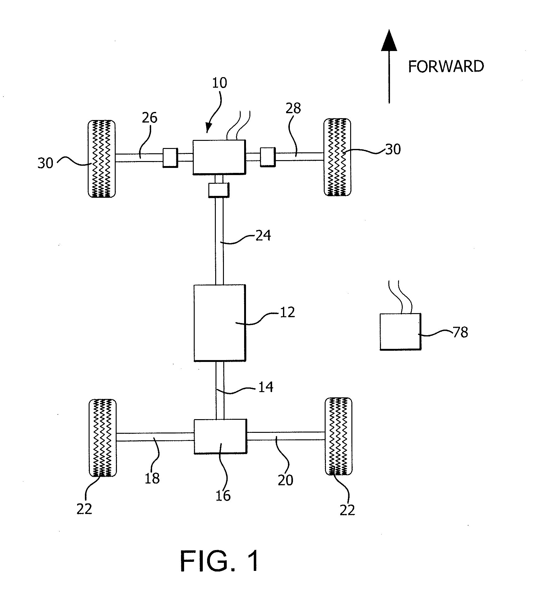
[0040]Referring now to the drawings, wherein like reference numerals illustrate corresponding or similar elements throughout the several views, FIG. 1 is a schematic representation of one embodiment of a drive system incorporating a bi-directional overrunning clutch assembly 10 according to an embodiment of the present invention. The drive system includes a transmission 12, a primary drive shaft 14 a primary differential 16, and first and second primary driven shafts 18, 20 which drive primary wheels 22.

[0041]The drive system also includes a secondary drive shaft 24 which is rotatably connected to the bi-directional overrunning clutch assembly 10 through any conventional means known to those skilled in the art, such as a splined connection. The bi-directional overrunning clutch assembly 10, in turn, rotatably drives two secondary driven shafts 26, 28 which are attached to wheels 30.

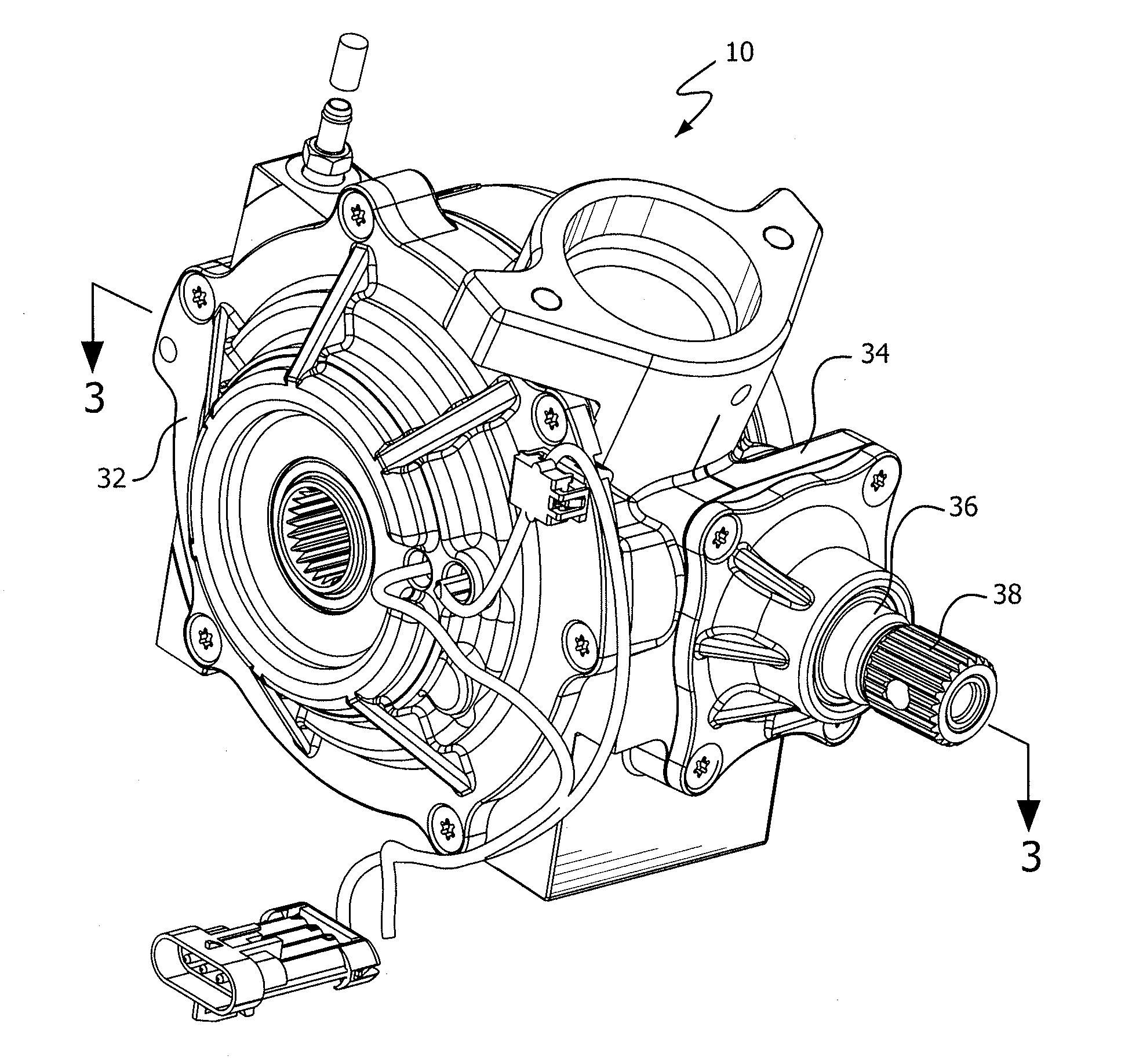
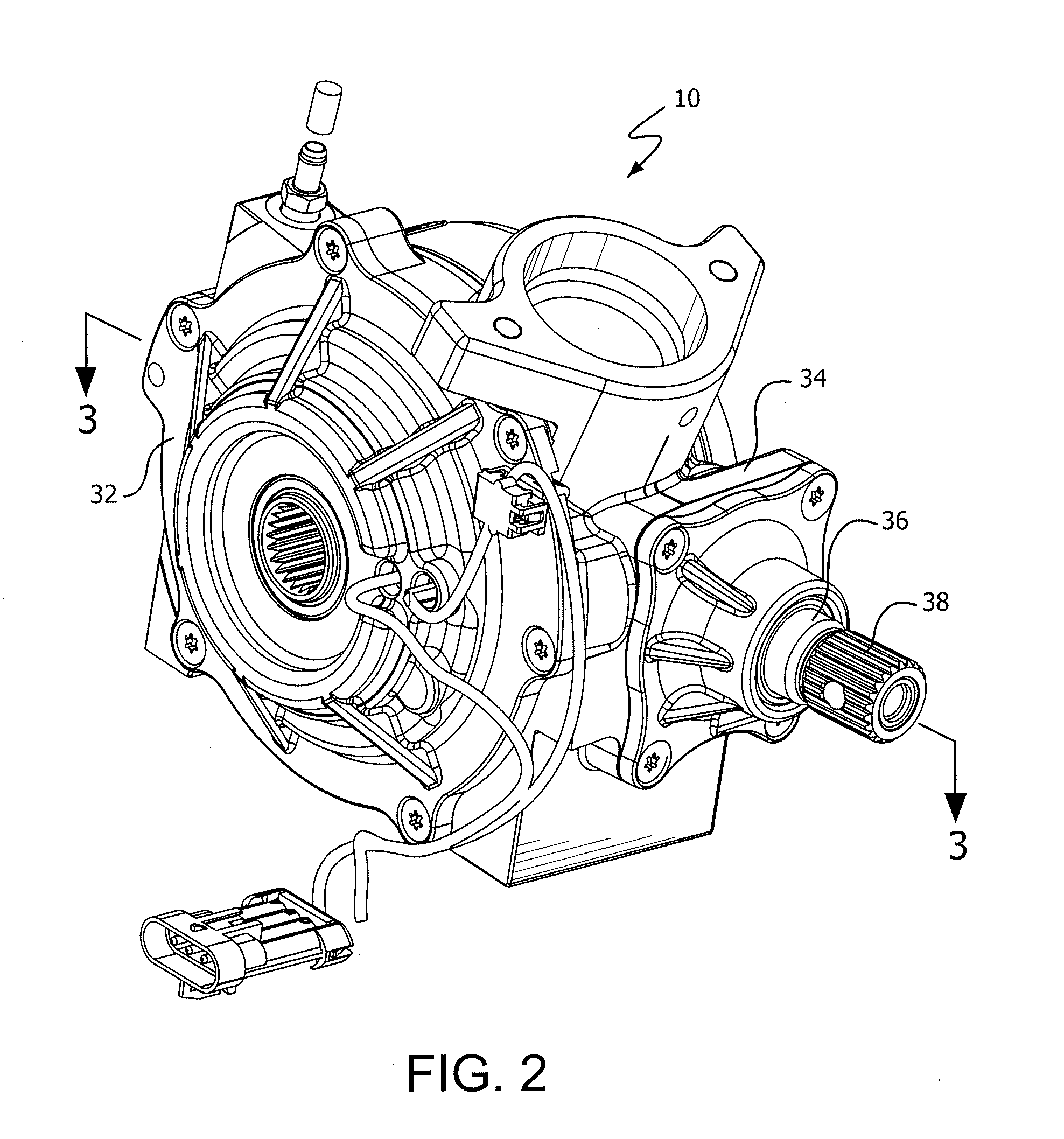
[0042]The details of the bi-directional overrunning clutch assembly will now be described with respect...


PUM


Abstract

A bi-directional overrunning clutch assembly for engaging secondary driven shafts in a four wheel drive vehicle. The assembly includes a differential housing with a pinion input gear rotatably disposed within it that is engaged to a drive shaft. A bi-directional overrunning clutch housing is engaged to the pinion gear. A roll cage assembly is located inside the clutch housing. A pair of hubs are positioned within the roll cage assembly and connected to the secondary driven shafts. An electromagnetic system controls indexes the roll cage in a first direction relative to the clutch housing a first indexing device for coupling the secondary drive shaft to the secondary driven axles when four wheel drive is needed, and in an opposite direction using a second indexing device when an engine braking condition is needed. A spring assembly is preferably used to bias the roll cage back to a neutral position.

Description

RELATED APPLICATION[0001]This is a non-provisional US patent application claiming priority to U.S. Provisional Patent Application 61 / 783,125, filed on Mar. 14, 2013, the disclosure of which is incorporated herein by reference in its entirety.FIELD OF THE INVENTION[0002]The present invention relates to clutches and, more particularly, to an electro-mechanical bi-directional overrunning clutch for providing four wheel drive capability.BACKGROUND OF THE INVENTION[0003]The increased demand in recent years for off-road and all terrain vehicles has led to tremendous developments in those types of vehicles. Many of the developments have centered around making the vehicle more adaptable to changing road conditions, e.g., dirt roads, pavement and gravel. As the road terrain changes, it is desirable to vary the driving capabilities of the vehicle to more efficiently navigate the new terrain. Prior four-wheel drive and all terrain vehicles were cumbersome since they required the operator to ma...

Claims


Application Information

Patent Timeline
Patent Type & Authority Applications(United States)
IPC IPC(8): B60W10/02B60W10/12
CPCB60W10/12B60W10/02B60K17/26B60K17/3505F16D41/088F16D27/10F16H48/16F16D47/04
Inventor KNICKERBOCKER, HOWARD J.OCHAB, DAVID C.COWEN, MATHEW
Owner HILLIARD CORP
Why Eureka
Try Eureka