Auxiliary acid and sour gas treatment system and method

a technology of auxiliary acid and sour gas, which is applied in the field of oil and gas refining, can solve the problems of inability to meet the requirements of downstream capacity, processing may occur at very low absolute pressure, and the regeneration of solvents used and stored by the present auxiliary system may be delayed indefinitely, so as to reduce the need for capital, promote the overall operation efficiency of the primary gas treatment facility, and minimize flare emissions and associated waste gases

Active Publication Date: 2014-09-18
ZINK DONALD LAWRENCE
View PDF1 Cites 18 Cited by
  • Summary
  • Abstract
  • Description
  • Claims
  • Application Information

AI Technical Summary

Benefits of technology

[0026]The present auxiliary system may be used to treat sour gas prior to flaring when the primary gas treatment facility is partially or fully offline or inoperable, when such primary system or the refinery itself is starting up or shutting down, or where the feed is inappropriate for the gas treatment facility, such as during an upstream malfunction. In addition, the present auxiliary system may be used to smooth the processing load to better match downstream processing capabilities and capacity of the primary sour gas treatment system with upstream demand surges, thereby minimizing flare emissions and associated waste gases. Further, the auxiliary system of the present invention may be implemented to promote the ove

Problems solved by technology

Notably, the primary regeneration and primary gas treatment facilities may, but need not, be operational simultaneously with the present auxiliary sour gas treatment system and/or other flare minimization stages of the process, and the regeneration of the solvent used and stored by the present auxiliary system may be delayed indefinitely.
With larger volumes of solvent, processing may occur at very low absolute pressures, limited by the vapor pressure of the solvent and the vapor pressure of hydrogen sulfid

Method used


Image

  • Auxiliary acid and sour gas treatment system and method
  • Auxiliary acid and sour gas treatment system and method
  • Auxiliary acid and sour gas treatment system and method

Examples


Embodiment Construction

[0034]The following detailed description of the present invention references the accompanying drawing figures that illustrate specific embodiments in which the invention can be practiced. The embodiments are intended to describe aspects of the present invention in sufficient detail to enable those skilled in the art to practice the invention. Other embodiments can be utilized and changes can be made without departing from the spirit and scope of the present invention. The present invention is defined by the appended claims and, therefore, the description is not to be taken in a limiting sense and shall not limit the scope of equivalents to which such claims are entitled.

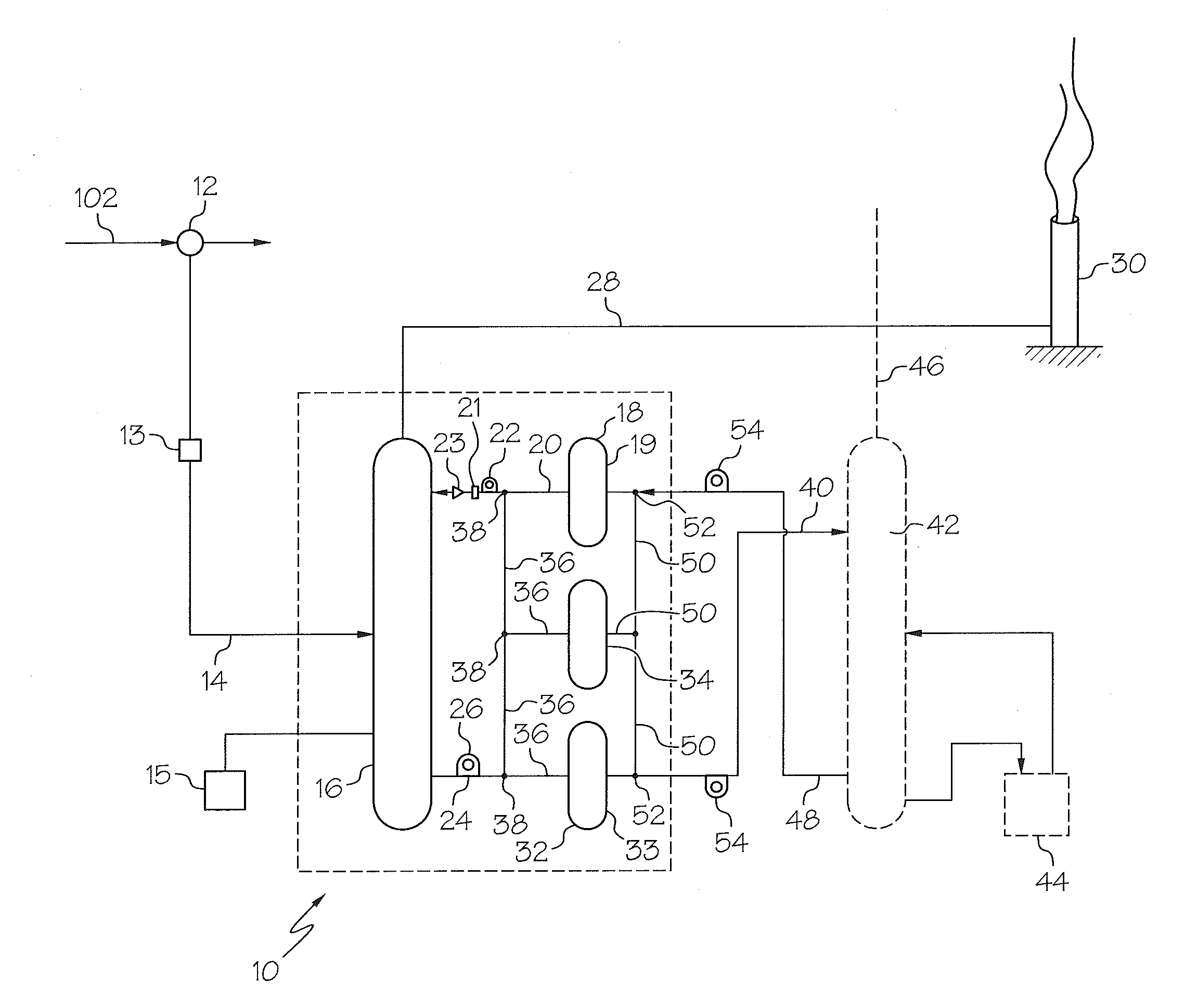
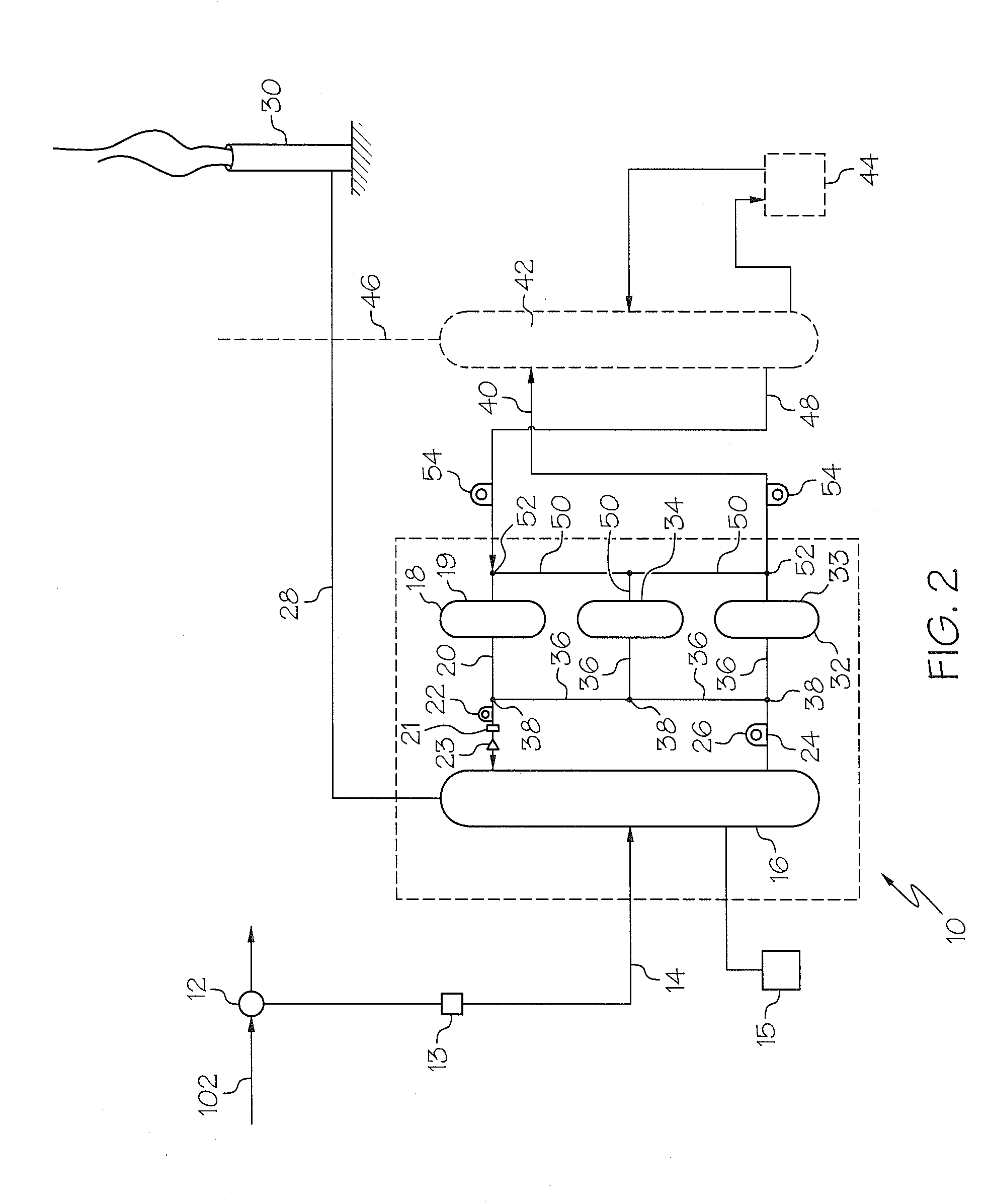
[0035]The present invention mitigates and / or prevents sulfur dioxide and hydrogen sulfide emissions from being introduced into the atmosphere through flaring untreated sour gas during a triggering event through a simple, scalable process which may be passive or active and that is readily installed and integrated into...


PUM

PropertyMeasurementUnit
Temperatureaaaaaaaaaa
Timeaaaaaaaaaa
Chemical propertiesaaaaaaaaaa

Abstract

An auxiliary sour gas treatment system for treating a stream of sour gas during a time wherein a primary gas treatment facility is unavailable, malfunctioning, inadequate or inoperable. The auxiliary sour gas treatment system comprises a lean solvent storage system to store an appreciable volume of a regenerable lean solvent available on demand. A scrubber to treat an influent supply of the sour gas by contacting the sour gas and the lean solvent which chemically or physically binds the contaminants in the sour gas resulting in a cleaned gas suitable for disposal or use as a fuel, and the solvent in an enriched state that contains the removed contaminants. The enriched solvent resulting from treatment may be stored indefinitely in a rich solvent storage system and then regenerated at any convenient time and at any convenient rate or place to remove the contaminants from the rich solvent.

Description

CROSS-REFERENCE TO RELATED APPLICATIONS[0001]This application claims the benefit of U.S. Provisional Patent Application No. 61 / 781,357, filed Mar. 14, 2013, the entire disclosure of which is hereby incorporated by reference.BACKGROUND OF THE INVENTION[0002]1. Field of the Invention[0003]The present invention is in the field of oil and gas refining and, particularly, the processing of sour natural gas and / or sour or acid gas by-products of an oil or natural gas refinery by a primary gas treatment facility and more particularly, in utilizing an auxiliary gas treatment system to manage flare emissions for mitigation of pollution and compliance with emission limitations.[0004]2. Description of Related Art[0005]When crude oil or sour natural gas is extracted from the ground, it must be refined to deliver a commercially distributable fuel and / or other products. Oil and gas refining typically involves several steps including the generation or production of waste gas and safe disposal of th...

Claims


Application Information

Patent Timeline
IPC IPC(8): C10L3/10B01D53/18B01D53/14
CPCC10L3/102B01D53/18B01D53/1431B01D53/1462B01D2252/103B01D2252/20405B01D2257/304B01D2257/504
Inventor ZINK, DONALD LAWRENCE
Owner ZINK DONALD LAWRENCE
Why Eureka
Try Eureka