
Resuscitation device with onboard processor

a resuscitation device and processor technology, applied in the field of manual resuscitation devices, can solve the problems of more difficult to inflate the lungs, risk of over-inflating the lungs, and pressure damage to the lungs

Active Publication Date: 2014-09-18
SUNMED GRP HLDG LLC
View PDF7 Cites 31 Cited by
  • Summary
  • Abstract
  • Description
  • Claims
  • Application Information

AI Technical Summary

Benefits of technology

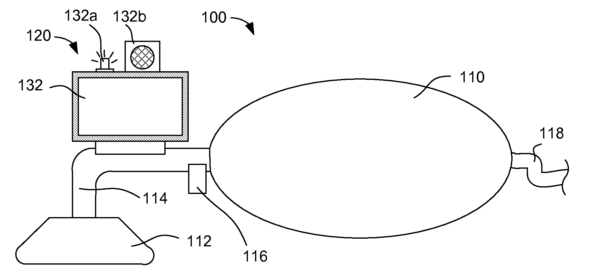
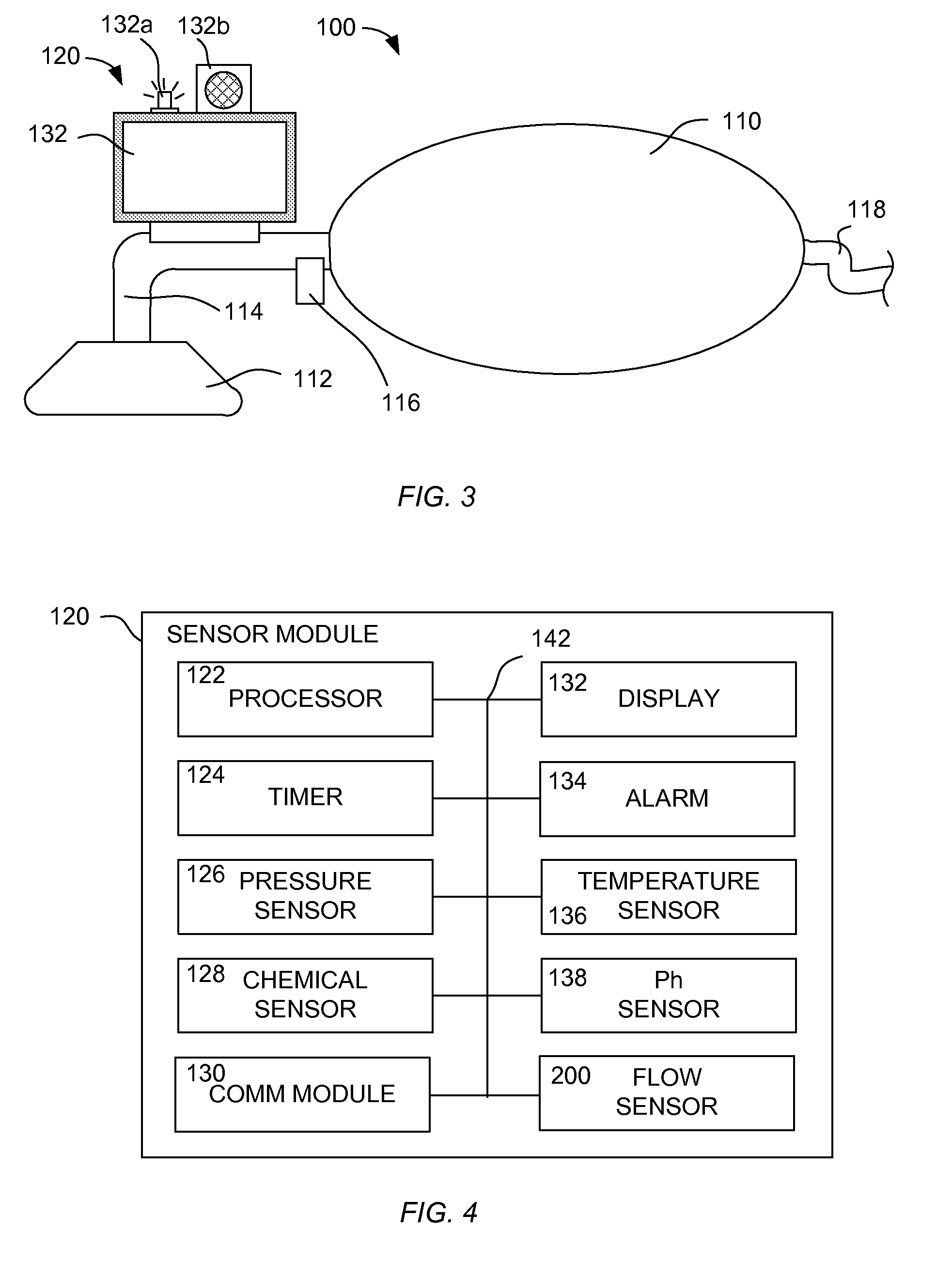
The patent describes a resuscitator device that can automatically monitor various aspects of patient's operation and breathing. The information gathered can be provided in real-time to a caregiver to aid in resuscitation efforts or stored for later review. The device includes a patient airway interface device, a bag, a flow passage, and a sensor assembly with a display and at least one sensor to measure various parameters, such as flow rate, pressure, temperature, pH, and chemical markers in the patient's breath. The sensor assembly can actuate an indicator based on the received measurement, providing information related to the patient's breath rate, tidal volume, pressure-vs-time curve, presence of chemicals, or patient condition. The technical effect of the invention is to provide a more efficient and effective means for resuscmitation during emergency situations.

Problems solved by technology

When using a resuscitator, there is a risk of over-inflating the lungs.
This can lead to pressure damage to the lungs themselves and can also cause air to enter the stomach, causing gastric distension which can make it more difficult to inflate the lungs.
Over-inflation may also cause the patient to vomit, which can cause additional airway problems beyond the original breathing difficulty.
These types of mechanical gauges have limited resolution and reading such a gauge can be a challenge for caregivers as the gauge provides only an instantaneous reading and the caregiver cannot pay constant attention to the gauge as they may be performing other actions, for example striving to maintain a proper seal of the mask to the patient's face and monitoring other symptoms and aspects of the patient's condition.

Method used


Image

  • Resuscitation device with onboard processor
  • Resuscitation device with onboard processor
  • Resuscitation device with onboard processor

Examples


Embodiment Construction

[0024]The resuscitator disclosed herein provides automatic monitoring of various aspects of the operation of the resuscitator as well as the patient's breathing and exhaled breath. The information gathered by the resuscitator can be provided in real-time to the caregiver to aid in their resuscitation efforts or stored for later review and analysis.

[0025]In general, the disclosed resuscitator may include sensors that continuously or intermittently measure the pressure within the patient airway interface device and, during an exhalation by the patient, may measure one or more of chemical markers or particular chemicals, temperature, or pH. The resuscitator may also provide guidance to the caregiver such as a metronome of the optimal rate of inhalations, visual or audible alarms, and verbal communication.

[0026]This disclosure describes embodiments that include a mask intended to be placed over a patient's nose and / or mouth so as to form a sealed connection to the patient's airway. It s...


PUM


Abstract

A resuscitator has a patient airway interface device, a bag, a flow passage coupled between the bag and patient airway interface device, and a sensor assembly. The patient airway interface device may be a mask or an endotracheal tube. The sensor assembly has a display, at least one sensor coupled to the flow passage and configured to provide a measurement of at least one parameter, and a processor coupled to the display and the at least one sensor. The processor is configured to receive the measurement from the sensor and provide information on the display based on the received measurement. The information may include a current breath rate, a pressure-vs-time curve, and guidance to the user to assist in achieving a target breath rate.

Description

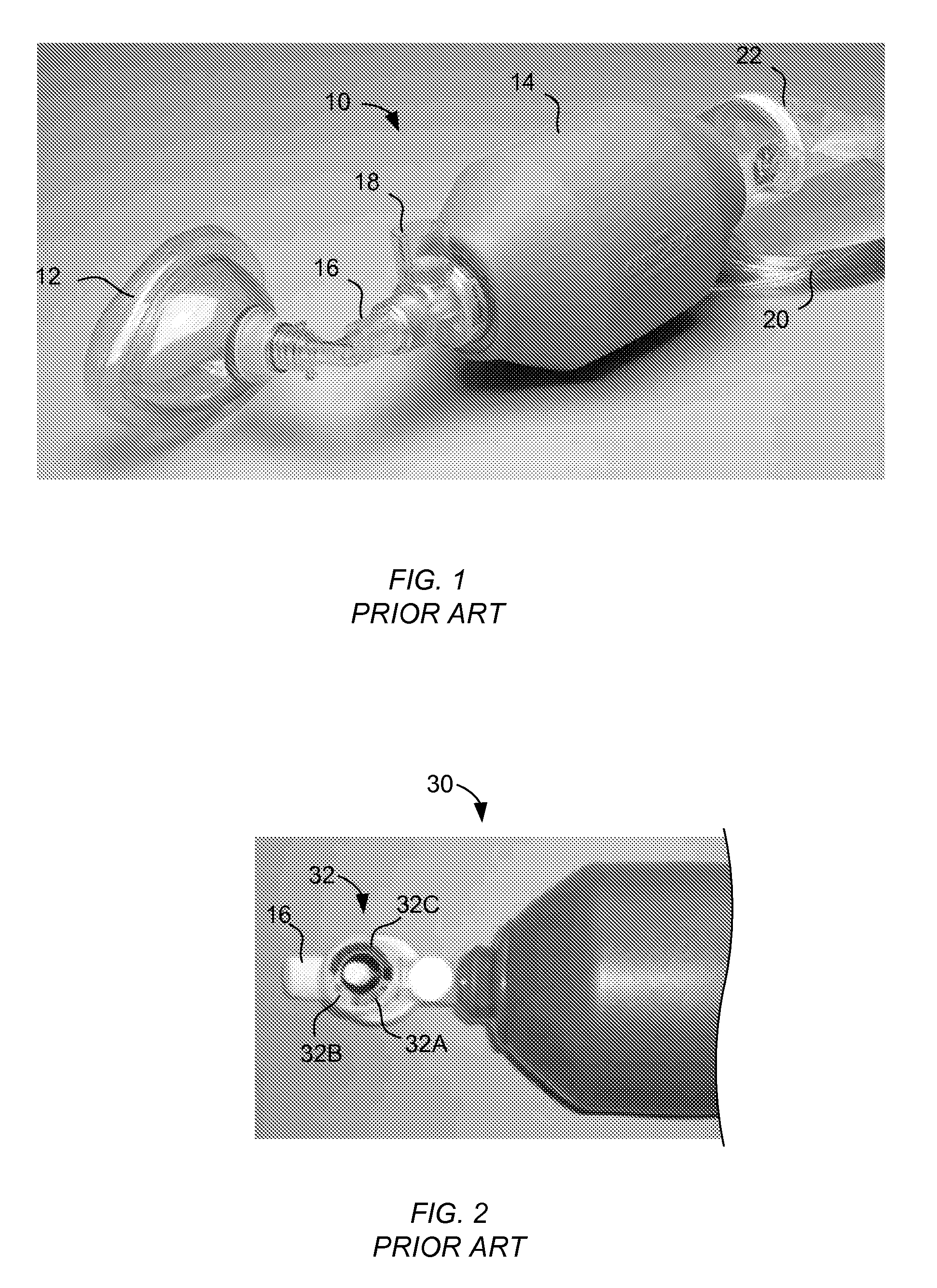
CROSS-REFERENCES TO RELATED APPLICATIONS[0001]Not applicable.BACKGROUND[0002]1. Field[0003]The present disclosure generally relates to manual resuscitation devices and, in particular, a resuscitator that incorporates electronic sensing and processing.[0004]2. Description of the Related Art[0005]A resuscitator, sometimes referred to as a bag valve mask (BVM) or by the proprietary name “Ambu bag,” is a hand-held device used to provide positive pressure ventilation to a patient who is not breathing or who is breathing inadequately. The resuscitator is a normal part of a “crash cart” used within a hospital or a resuscitation kit provided to ambulance crew. A resuscitator may also be used in an operating room to ventilate an anaesthetized patient prior to attachment of a mechanical ventilator. A resuscitator may be self-filling with air or provided with a source of breathing gas, such as oxygen, to increase the oxygenation of the patient.[0006]FIG. 1 depicts a conventional resuscitator 1...

Claims


Application Information

Patent Timeline
IPC IPC(8): A61M16/00A61M16/06A61M16/04A61B5/087A61B5/08A61B5/01A61B5/00A61B5/03
CPCA61M16/0078A61B5/0004A61B5/01A61B5/03A61B5/082A61B5/087A61M16/06A61B5/72A61B5/7405A61B5/742A61B5/746A61M16/04A61B5/4836A61M16/0051A61M2016/0033A61M2205/3592A61M2205/50A61M2205/502A61M2205/581A61M2205/583A61M16/0084A61M2202/0208A61M16/208A61M2016/0021A61M2016/0027A61M2205/3303A61M2205/3324A61M2205/3368A61M2205/52A61M2205/8212A61M2230/42A61M2230/432A61B5/74A61B5/0002A61B5/0876A61M16/024A61B5/0022A61B5/0816A61B5/091A61M2205/3584A61M2205/505
Inventor VARGA, CHRISTOPHERWHITE, DENNISMCMAHON, MICHAEL
Owner SUNMED GRP HLDG LLC
Learn More