Retention Cuff for Bowel Management System

a technology of bowel management system and retention cuff, which is applied in the field of irregular shaped inflatable retention cuff or balloon, and can solve the problems of cuff leakage, balloon shape is not designed to conform, and retention cuffs are also known to leakag

Inactive Publication Date: 2014-09-18
HOLLISTER INCORPORAED
View PDF6 Cites 3 Cited by
  • Summary
  • Abstract
  • Description
  • Claims
  • Application Information

AI Technical Summary

Benefits of technology

[0015]In one example, the interior volume can be filled with a medium to a less than fully expanded state whereby the body is in a floppy or flaccid condition.

Problems solved by technology

During use, these retention cuffs are also known to leak.
These prior know balloon shapes are not designed to conform to the human anatomy to the extent that the device can account for the “anorectal angle” of a patient.
In other words, no known devices take into account, in their design configuration, the angle created by the kink in the lower gastro-intestinal tract that prevents incontinence in an upright walking person.
Thus, the cuff can leak and the catheter can migrate in and out, and even can result in frequent expulsion of the catheter from the patient's anus.
However, adding more fluid to the retention cuff often does not reduce leaking or expulsion frequency but does cause discomfort and even injury to the patient.
This does not aid in cuff retention or in preventing leaks and can increase the risk of the central opening through the balloon becoming occluded.
These solutions have proven less than adequate in solving the foregoing problems.
This type of spontaneous expulsion is quite undesirable.
One disadvantage of providing a stiff annulus, however, is that depending on the design, the edges of the annulus can create points of stress concentration in the device.
These points or edges can potentially cause irritation or damage to the patient's body where these edges come into contact with the rectal wall.
Another problem with these prior known retention cuffs is that in part, due to the anorectal angle, the rectal wall can partially occlude the opening of the annulus during use of the product.
Heretofore, there has been no elegant or adequate solution to this problem.

Method used


Image

  • Retention Cuff for Bowel Management System
  • Retention Cuff for Bowel Management System
  • Retention Cuff for Bowel Management System

Examples


Embodiment Construction

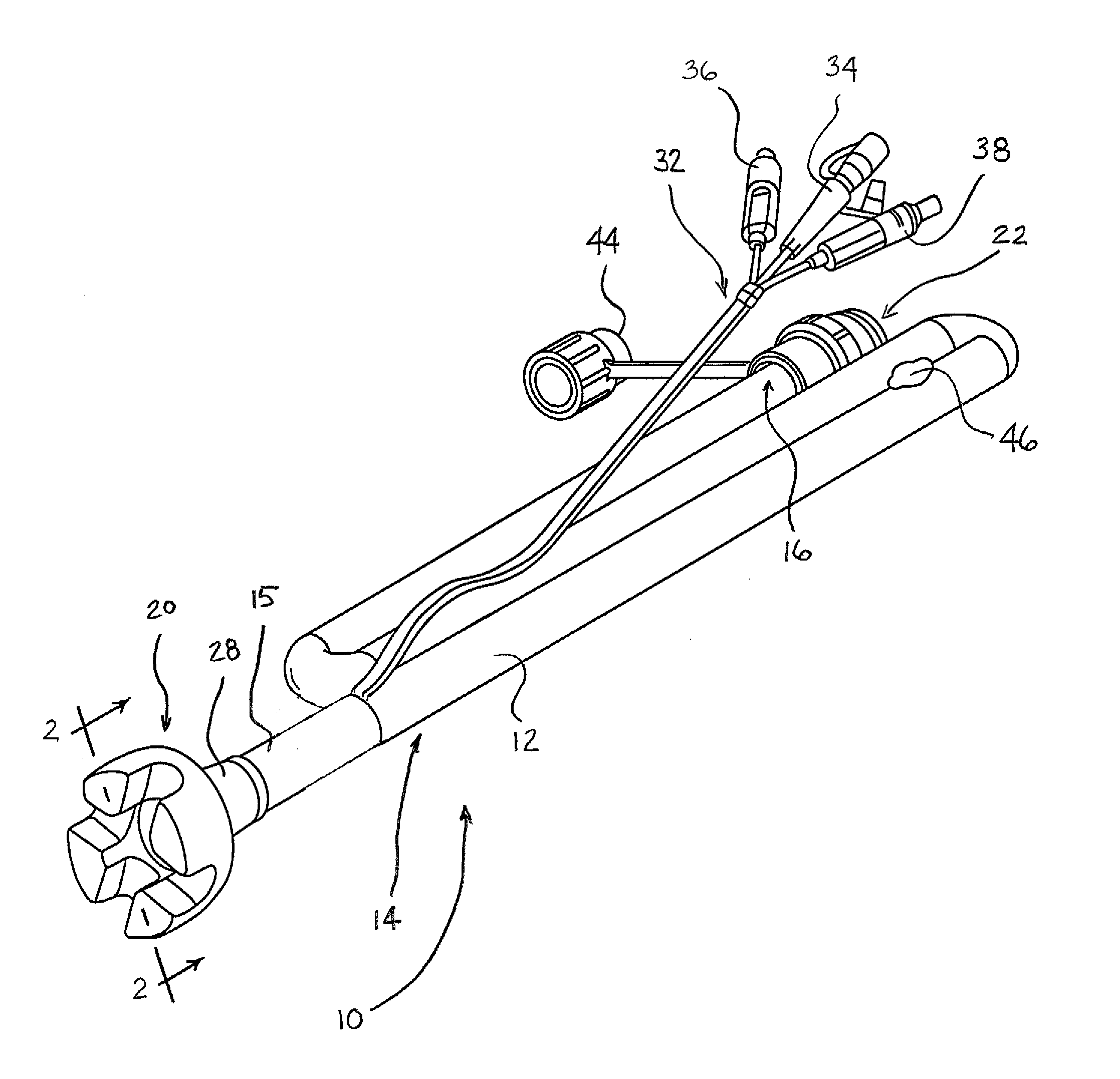
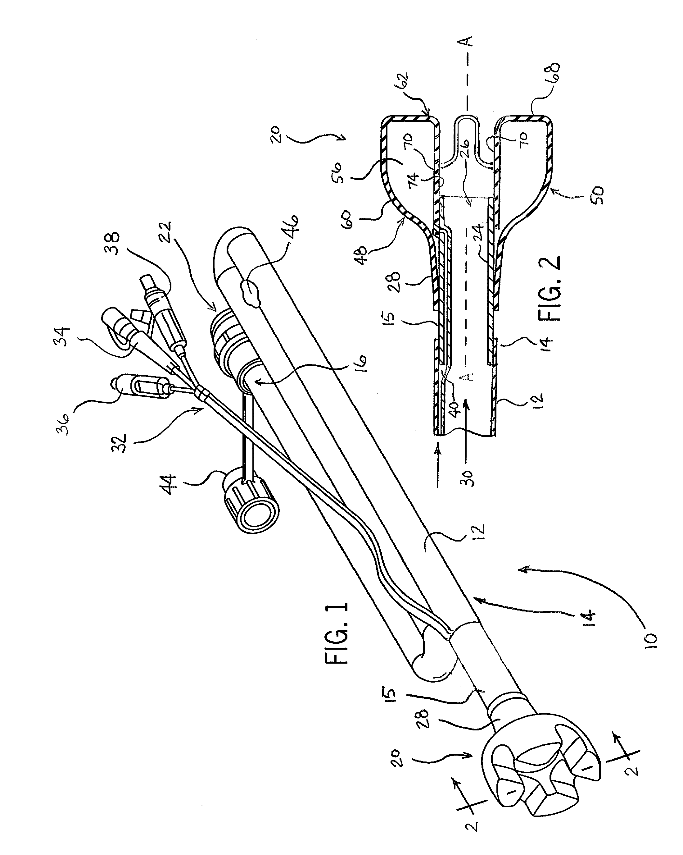
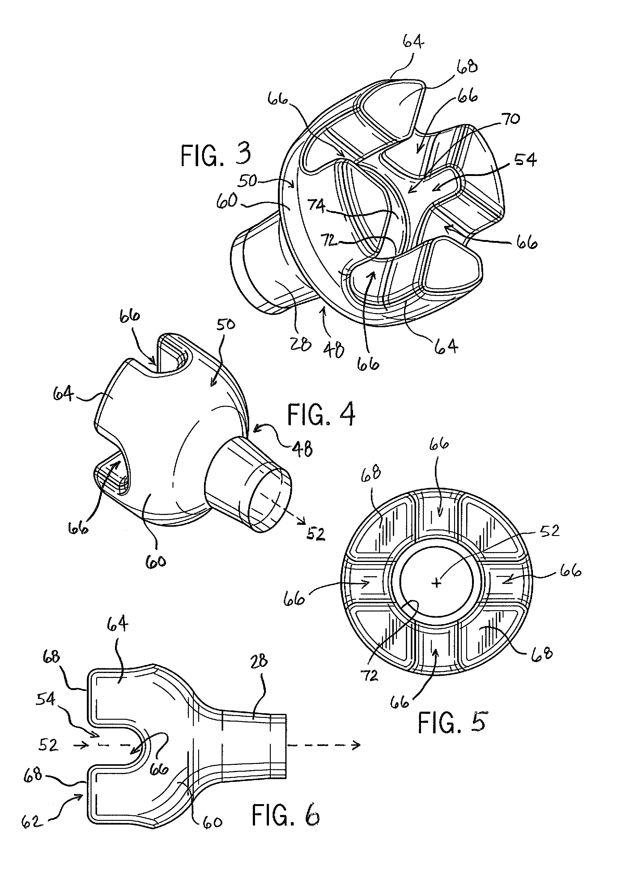
[0040]Examples of a retention cuff or rectal catheter balloon are disclosed herein and each is hereinafter referred to as a retention cuff. The disclosed retention cuffs, when filled properly, are flaccid or somewhat “floppy” rather than turgid or stiff. Prior known balloons or cuffs are turgid when filled. The present disclosure is also for a retention cuff having an irregular shape with lateral flow sub-channels, pathways, openings, or the like. The disclosed retention cuff embodiments solve or improve upon one or more of the above-noted and / or other problems and disadvantages with prior known retention cuffs and rectal catheter systems.

[0041]The disclosed retention cuffs provide fluid filled space that is a cushion between the stiff annulus edges of the drainage tube or bowel catheter and the rectal tissue of a patient. The disclosed retention cuff also provides openings, sub-channels, flow pathways, or the like in the inflated balloon or cuff that are generally perpendicular to ...


PUM


Abstract

A retention cuff for a fecal collection device has an inflatable body with a proximal end, a proximal end flow opening, a free end, and a free end flow opening. An interior volume within the body is fillable with a medium to inflate the cuff. An axial flow path extends along an axis of and through the body and is in flow communication with the proximal and free end openings. A plurality of lateral flow pathways in the body are in flow communication with the axial flow path. The plurality of lateral flow pathways provides fluid flow in a direction different from the axial flow path.

Description

RELATED APPLICATION DATA[0001]This patent is related to and claims priority benefit of U.S. provisional application Ser. No. 61 / 917,201 filed Dec. 17, 2013 and U.S. provisional application Ser. No. 61 / 790,162 filed Mar. 15, 2013, each having the same title as the instant application. The entire content of these prior filed provisional applications is hereby incorporated herein by reference.BACKGROUND OF THE DISCLOSURE [0002]1. Field of the Disclosure[0003]The present disclosure is generally directed bowel management systems, and more particularly to an irregular shaped inflatable retention cuff or balloon for a bowel drainage tube or a bowel catheter for same.[0004]2. Description of Related Art[0005]Commercially available drainage tubes for bowel management systems and fecal collection devices are known to include a generally spheroidal or spherical retention cuff or balloon at the free, patient insertion end of the tube. During use, these retention cuffs are also known to leak. Suc...

Claims


Application Information

Patent Timeline
Patent Type & Authority Applications(United States)
IPC IPC(8): A61F5/44
CPCA61F5/4408A61M2202/068A61F5/0093A61F5/4405A61F5/451A61F2005/4455
Inventor CISKO, GEORGE J.GILMAN, THOMAS H.CULLUM, MALFORD EUGENEMURAHATA, RICHARD I.
Owner HOLLISTER INCORPORAED
Why Eureka
Try Eureka