Cross-braced bilateral spinal rod connector

a cross-braced, spinal rod technology, applied in the field of cross-braced bilateral spinal rod connectors, can solve the problems of limiting the range of motion of the spinal cord, spinal pathologies, etc., and achieve the effects of reducing the stress concentration/overload of the rod itself, reducing the stress shielding and overload of adjacent joints, and reducing the stress of the rod itsel

Inactive Publication Date: 2014-09-18
BLACKSTONE MEDICAL
View PDF4 Cites 33 Cited by
  • Summary
  • Abstract
  • Description
  • Claims
  • Application Information

AI Technical Summary

Benefits of technology

[0016]The benefits of this device over conventional head-to-head connectors is the bracing provided at the unsupported span between the support rods to distribute loading to adjacent joints, contrary to conventional head-to-head connectors which only provide support to screws connected to the same vertebral body. As a result, conventional head-to-head connectors only create a stiffer vertebral body by maintaining a constant spacing between the pedicle screws. This distribution of load across adjacent joints alleviates stress shielding and overloading of adjacent joints.
[0017]Compared to older rod-to-rod connectors, the cross-braced version provides the same aforementioned stress distribution benefits and alleviates stress concentration / overloading of the rod itself due to the single load path inherent in the older rod-to-rod connector design.

Problems solved by technology

Genetic or developmental irregularities, trauma, chronic stress, tumors and disease, however, can result in spinal pathologies which either limit this range of motion or threaten the critical elements of the nervous system housed within the spinal column.

Method used


Image

  • Cross-braced bilateral spinal rod connector
  • Cross-braced bilateral spinal rod connector
  • Cross-braced bilateral spinal rod connector

Examples


Embodiment Construction

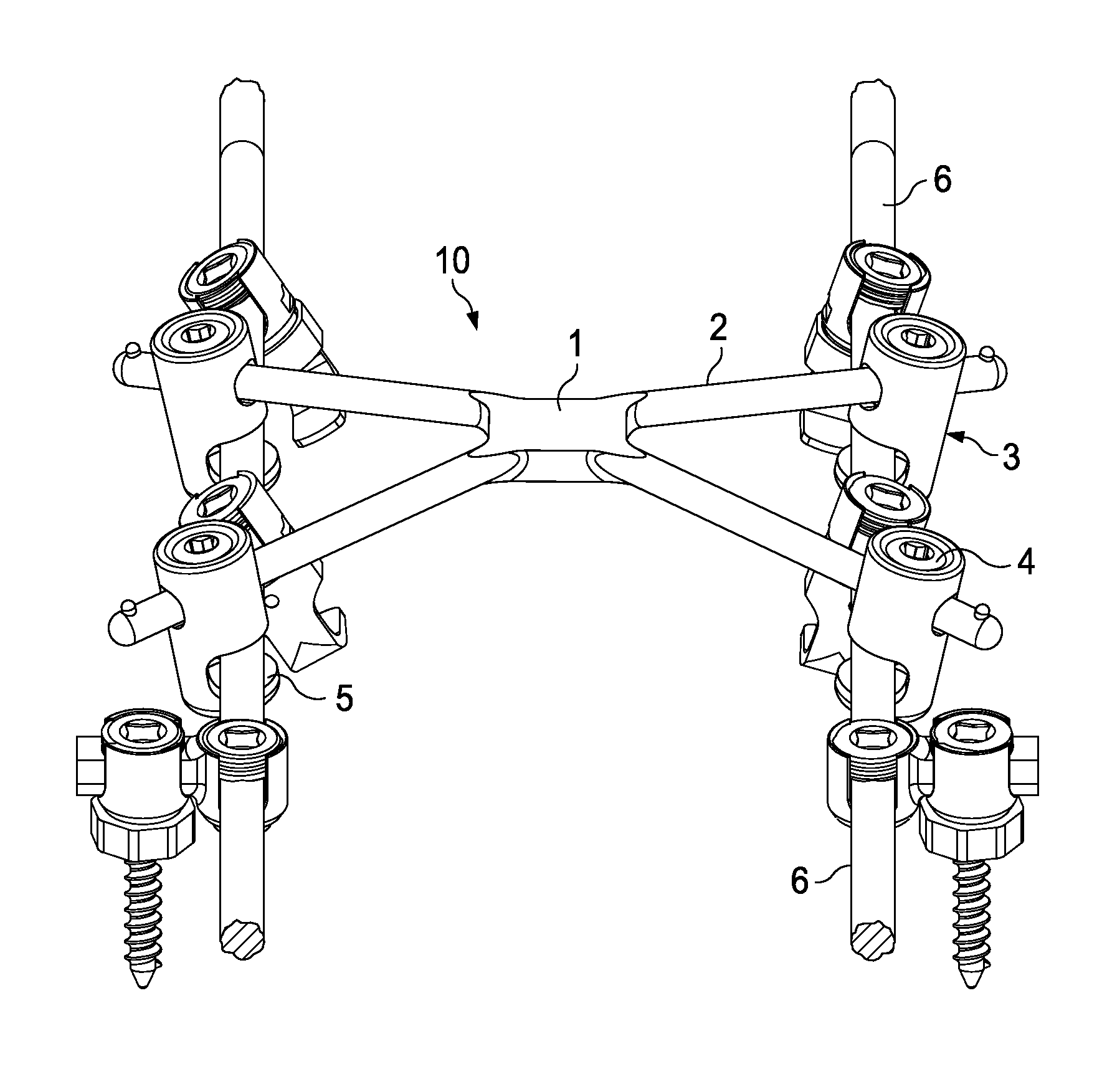
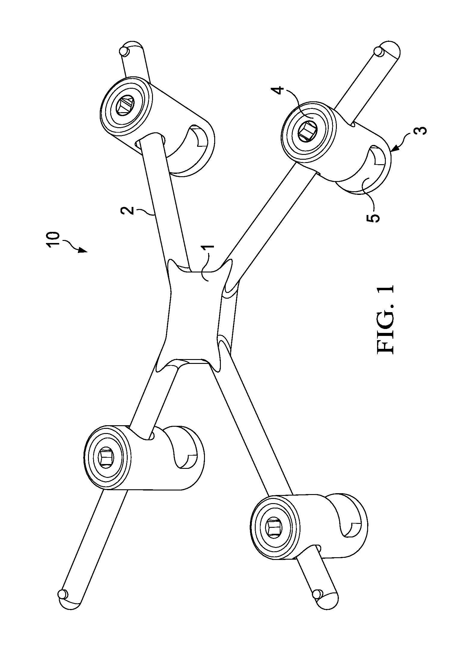
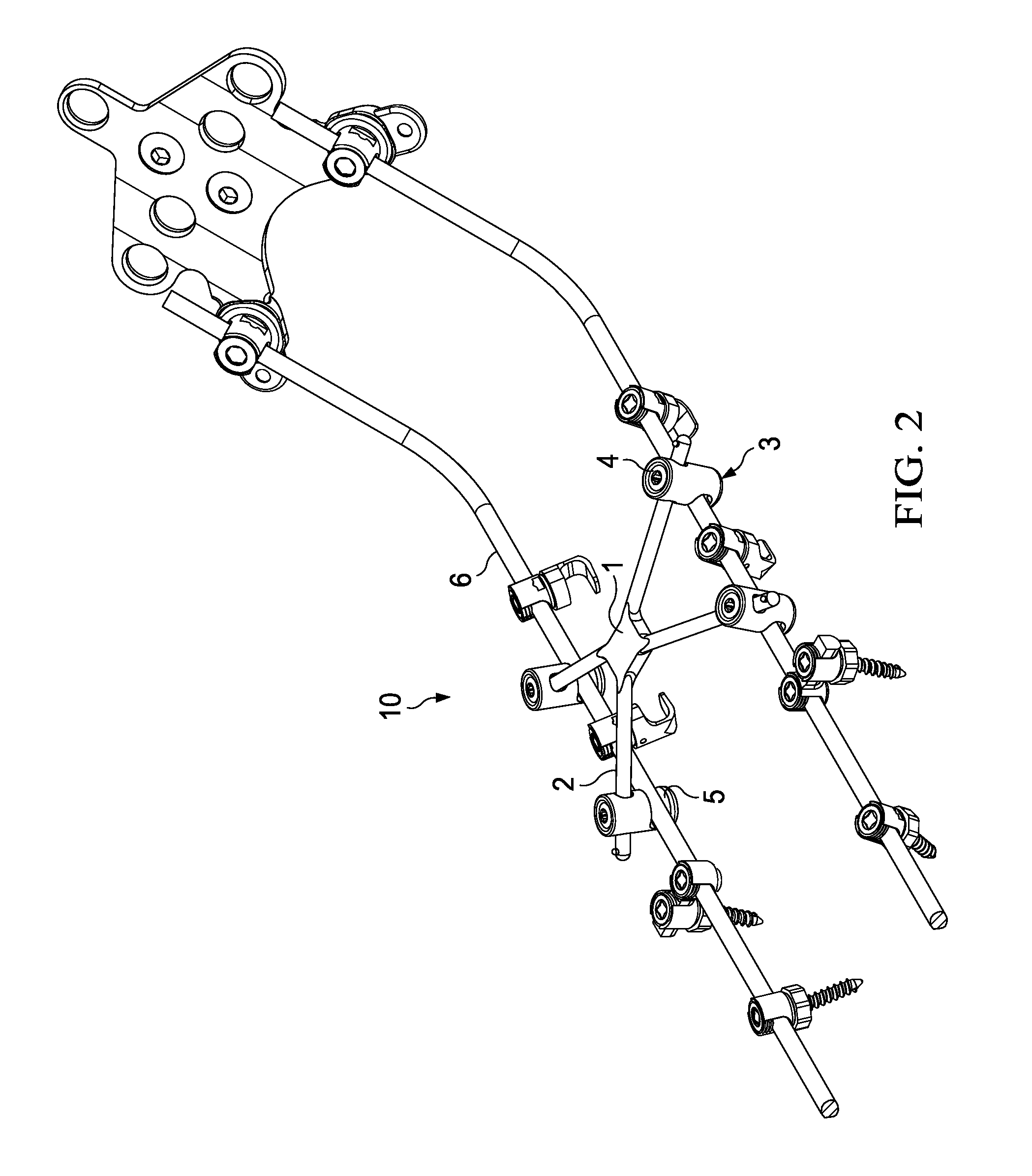
[0033]FIG. 1 illustrates an embodiment of a spinal rod connector apparatus (10). Here, a monolithic central member (1) has four extension legs (2). By forming the central member (1) and the extension legs (2) from a monolithic biocompatible material, such as surgical stainless steel or titanium, the strength and rigidity of the connector apparatus can be increased. In addition, by eliminating a mechanical interface between the central member (1) and the extension legs (2), the potential for weakening, metal fatigue, or loosening of the interface between the central member (1) and the extension legs (2) can be reduced. This improves the effective lifetime of the device (10).

[0034]Attached to each extension leg (2) is a connecting member (3) comprising a set-screw (4) and a slot (5). Each connecting member (3) is capable of translating along the longitudinal axis of the associated extension leg (2). Further, each connecting member (3) is capable of complete rotation about the axis of ...


PUM


Abstract

A spinal rod connector apparatus for use with spinal implantation rods and methods of securing implantation rods using a cross-braced bilateral spinal rod connector apparatus. The spinal rod connector apparatus comprises a central member having two or more extension legs. The extension legs can be of varying lengths and disposed at varying angles with respect to the monolithic central member, depending upon physiological sizing requirements. Attached to each extension leg is a connecting member capable of connecting to a bilateral spinal rod construct.

Description

BACKGROUND[0001]The present disclosure relates to a support rod connector apparatus for use with, inter alia, spinal implantation rods and related methods of securing implantation rods using a cross-braced bilateral spinal rod connector apparatus. More particularly, this disclosure relates to a novel, cross-braced bilateral support rod connector that enhances the rigidity of bilateral spinal rods anchored to the spine.[0002]The bones and connective tissue of an adult human spinal column consists of more than 20 discrete bones coupled sequentially to one another by a tri-joint complex. The complex consists of an anterior disc and two posterior facet joints. The anterior discs of adjacent bones are cushioned by cartilage spacers referred to as intervertebral discs. The over 20 bones of the spinal column are anatomically categorized as one of four classifications: cervical, thoracic, lumbar, or sacral. The cervical portion of the spine which comprises the top of the spine up to the bas...

Claims


Application Information

Patent Timeline
Patent Type & Authority Applications(United States)
IPC IPC(8): A61B17/70
CPCA61B17/7052A61B17/7055
Inventor LI, NELSONLAROSA, FRANCESCO
Owner BLACKSTONE MEDICAL
Why Eureka
Try Eureka