Eureka AIR delivers breakthrough ideas for toughest innovation challenges, trusted by R&D personnel around the world.

Retention device for valve actuating mechanism

Active Publication Date: 2014-09-25
GT TECH INC
View PDF1 Cites 1 Cited by
  • Summary
  • Abstract
  • Description
  • Claims
  • Application Information

AI Technical Summary

Benefits of technology

The present invention provides a new retention device for a valve actuating mechanism. The retention device includes a connecting member that is below a ring member and can move freely in all pivoted positions of an actuating lever. This allows the connecting member to abut firmly on the finger follower in all operating positions of the valve actuating mechanism. The retention device ensures that the connecting member does not need to be enlarged during each individual valve lift, which would require additional power. This creates a more efficient and effective valve actuating mechanism.

Problems solved by technology

The above-described patented sheet metal retention clip suffers from the disadvantage that this clip always effects a relative movement in relation to the finger follower or the lash adjuster.
Another disadvantage is that the constant relative movement occurring between the retention clip and the finger follower and between the retention clip and the lash adjuster subjects the valve actuating mechanism to additional friction, which is undesired.
A further disadvantage of the retention clip is that it does not bear firmly against the finger follower in all operating positions of the valve actuating mechanism as a result of the pivoting motion of the finger follower.

Method used


Image

  • Retention device for valve actuating mechanism
  • Retention device for valve actuating mechanism
  • Retention device for valve actuating mechanism

Examples


Embodiment Construction

)

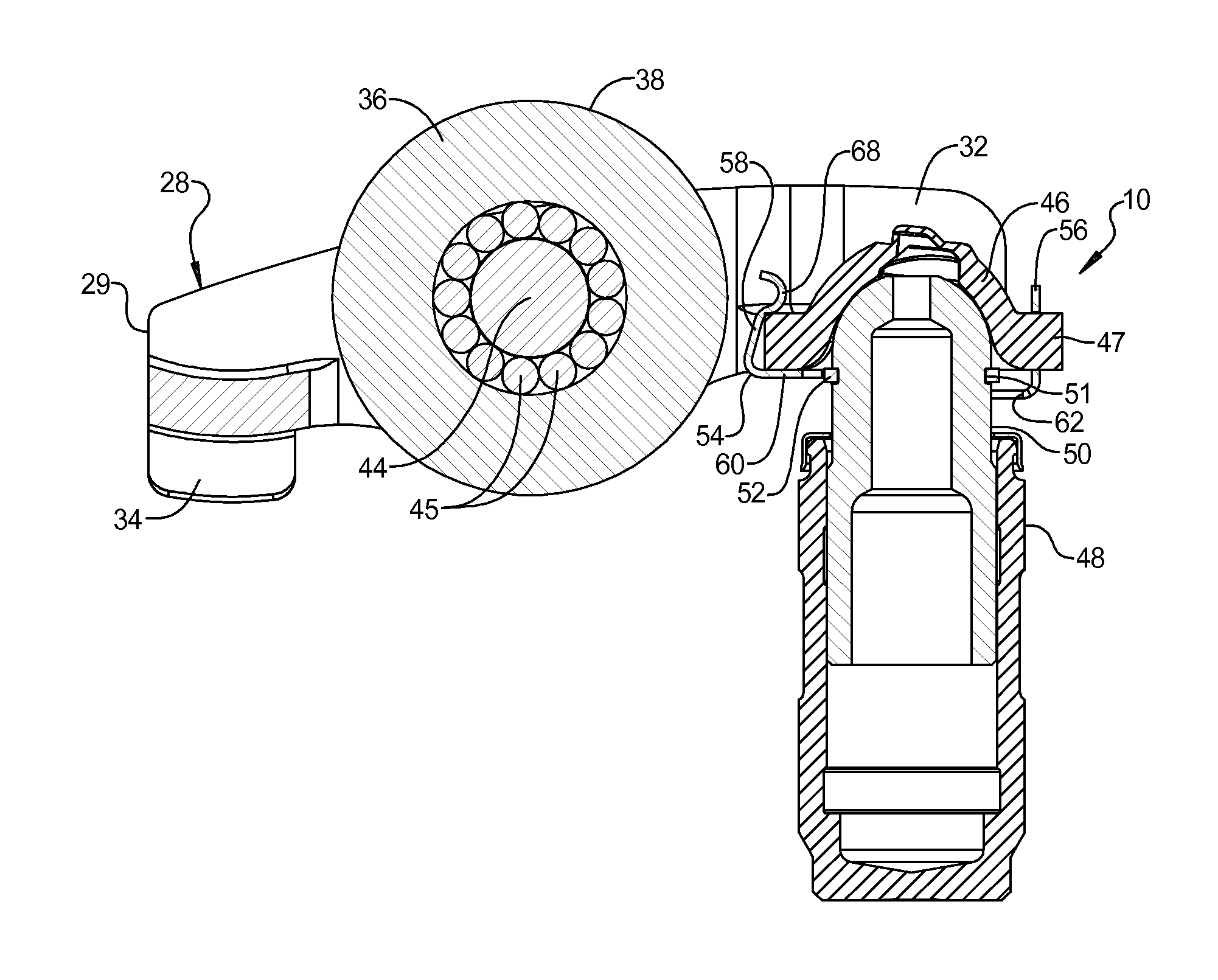
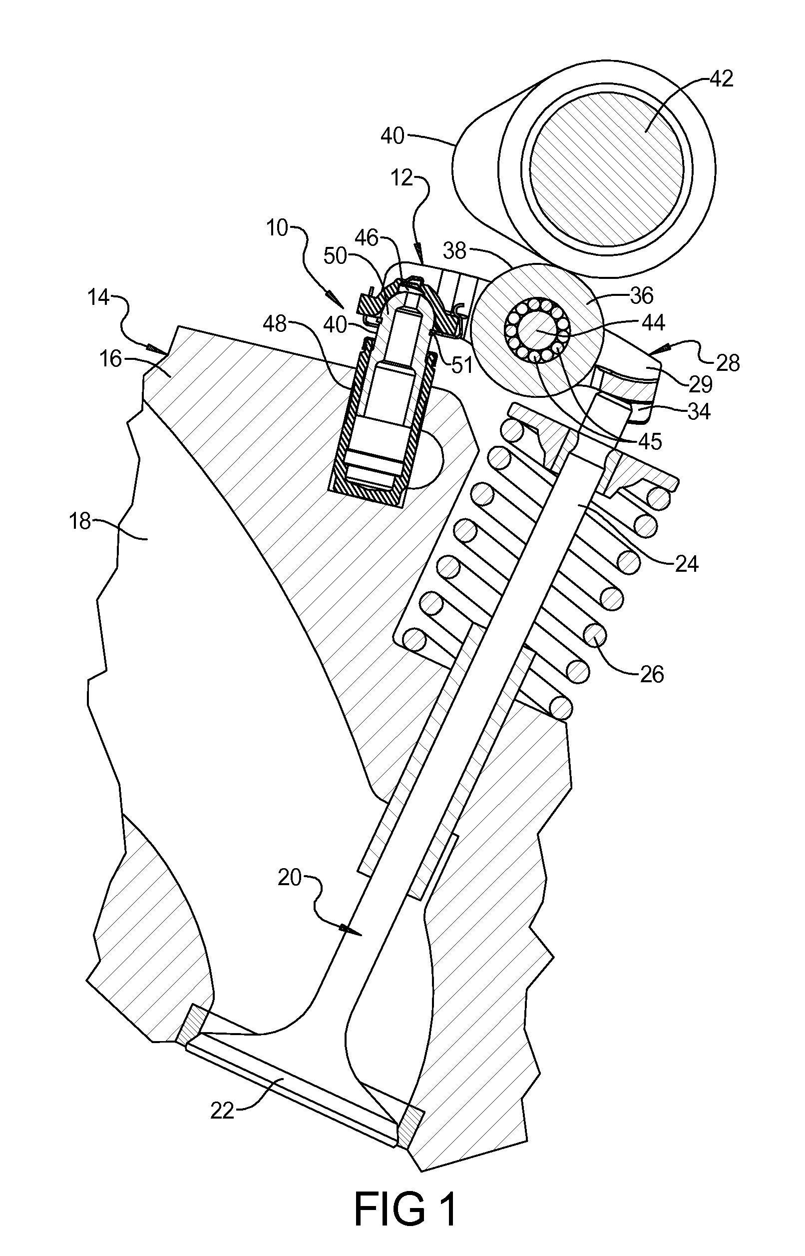
[0031]Referring now to the drawings, and in particular FIG. 1, one embodiment of a retention device 10, according to the present invention, for a valve actuating mechanism, generally indicated at 12, of a finger follower type is shown for an engine, generally indicated at 14. The engine 14 is of an overhead cam type having a cylinder head 16 including an inlet or exhaust port 18. The engine 14 also includes a valve 20 having a head 22 and a stem 24 extending from the head 22. The engine 14 includes a spring 26 disposed about the stem 24 that biases the head 22 of the valve 20 to a closed position. It should be appreciated that the engine 14 is conventional and known in the art.

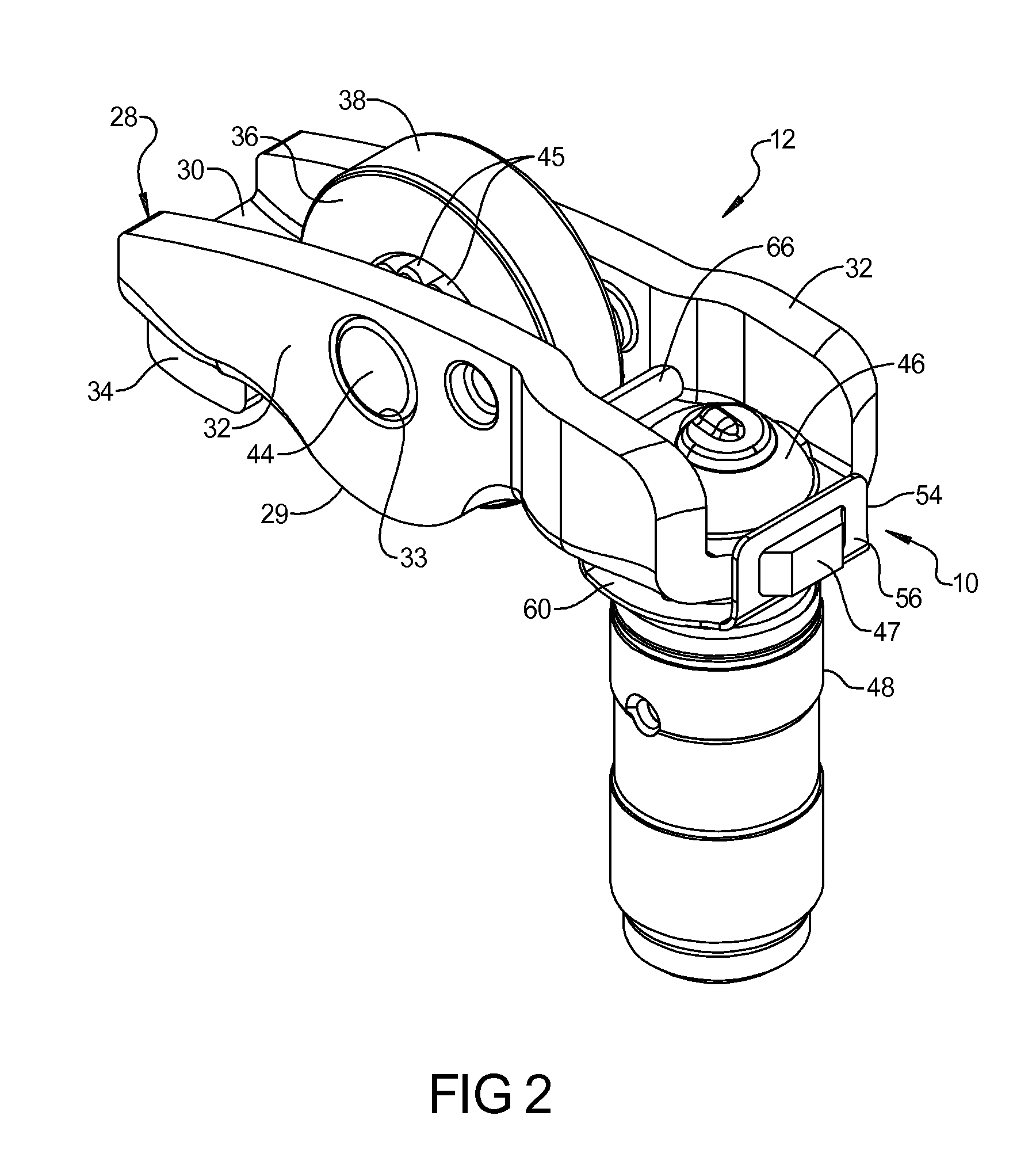
[0032]Referring to FIGS. 1 through 4, the valve actuating mechanism 12 includes an actuating lever or finger follower, generally indicated at 28, having a lever body 29 having a base wall 30 and a pair of opposed side walls 32 extending substantially parallel from the base wall 30 with an aperture 33 extendin...


PUM


Abstract

A retention device for a valve actuating mechanism to secure a finger follower and lash adjuster together includes a ring member disposed in a groove of a movable piston of the lash adjuster. The retention device also includes a connecting member having a plurality of legs adapted to engage the finger follower and an intermediate base interconnecting the legs and adapted to be disposed below the ring member and about a portion of the lash adjuster to effect a free movement of the connecting member in all pivoted positions of the finger follower.

Description

CROSS REFERENCE TO RELATED APPLICATIONS[0001]This application claims the benefit of U.S. provisional patent application entitled “Retention Device for Valve Actuating Mechanism,” having Ser. No. 61 / 804,796, and filed on Mar. 25, 2013.BACKGROUND OF THE INVENTION[0002]1. Field of the Invention[0003]The present invention relates generally to valve actuating mechanisms for engines and, more particularly, to a retention device for a valve actuating mechanism for an engine.[0004]2. Description of the Related Art[0005]It is known to provide valve actuating mechanisms to open and close valves of an engine such as an internal combustion engine. These valve actuating mechanisms may be of a finger follower type including a finger follower having a pallet or web engaging a stem of the valve and a dome socket engaging a rounded end of a hydraulic lash adjuster supported by a cylinder head of the engine. The dome socket is known to have a dome with a concave recess or socket therein. Typically, a...

Claims


Application Information

Patent Timeline
IPC IPC(8): F01L1/18
CPCF01L1/185F01L2001/187F01L1/2405
Inventor BRUNE, JOHN E.STOODY, IRA R.
Owner GT TECH INC
Why Eureka
Eureka Blog
Learn More