
Flowmeter

a flowmeter and flow rate technology, applied in the field of flowmeters, can solve the problems of high manufacturing cost, complex structure, and inability to effectively discharge air within the flowmeter, and achieve the effects of preventing beating, and reducing the pressure in the flowmeter

Active Publication Date: 2014-09-25
BEIJING AEONMED
View PDF5 Cites 1 Cited by
  • Summary
  • Abstract
  • Description
  • Claims
  • Application Information

AI Technical Summary

Benefits of technology

The invention is a new flowmeter for anesthesia machines that solves problems with existing flowmeters such as high manufacture costs, beating of the float, and excessive air resistance. The new flowmeter uses a pressure fluctuation suppressing assembly and a safety valve to prevent the float from beating and reduce air pressure when air resistance is excessive. Overall, the new flowmeter has a simple structure, low manufacture cost, and effective air discharge and pressure reduction.

Problems solved by technology

The existing flowmeter for the anesthesia machine has the following problems that: (1) the flowmeter float beats during the normal operation of the bellows of the anesthesia machine; (2) the air within the flowmeter cannot be discharged effectively in the case of excessive air resistance at the flowmeter outlet; and (3) its structure is complex and its manufacture cost is high.

Method used


Image

  • Flowmeter
  • Flowmeter
  • Flowmeter

Examples


Embodiment Construction

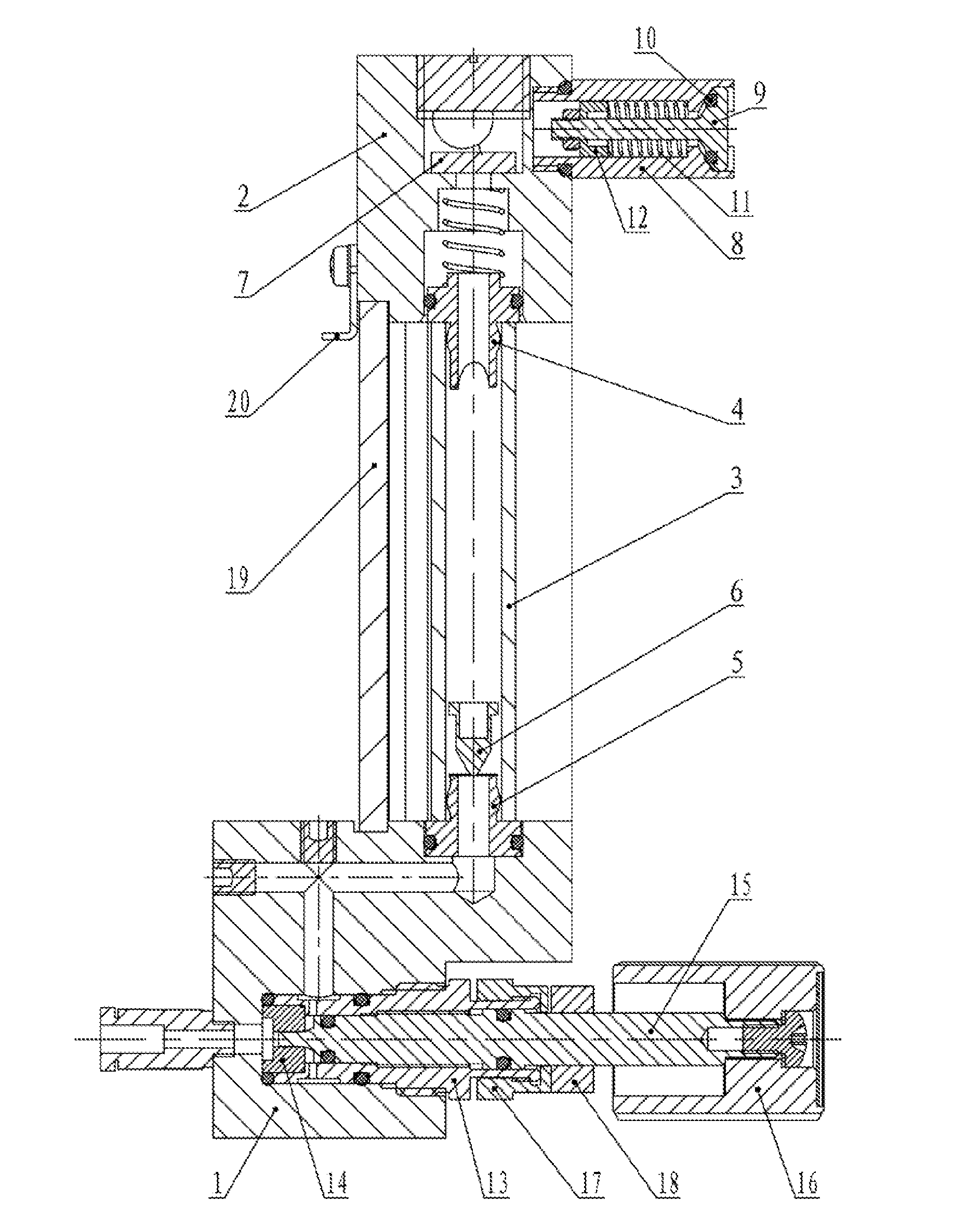
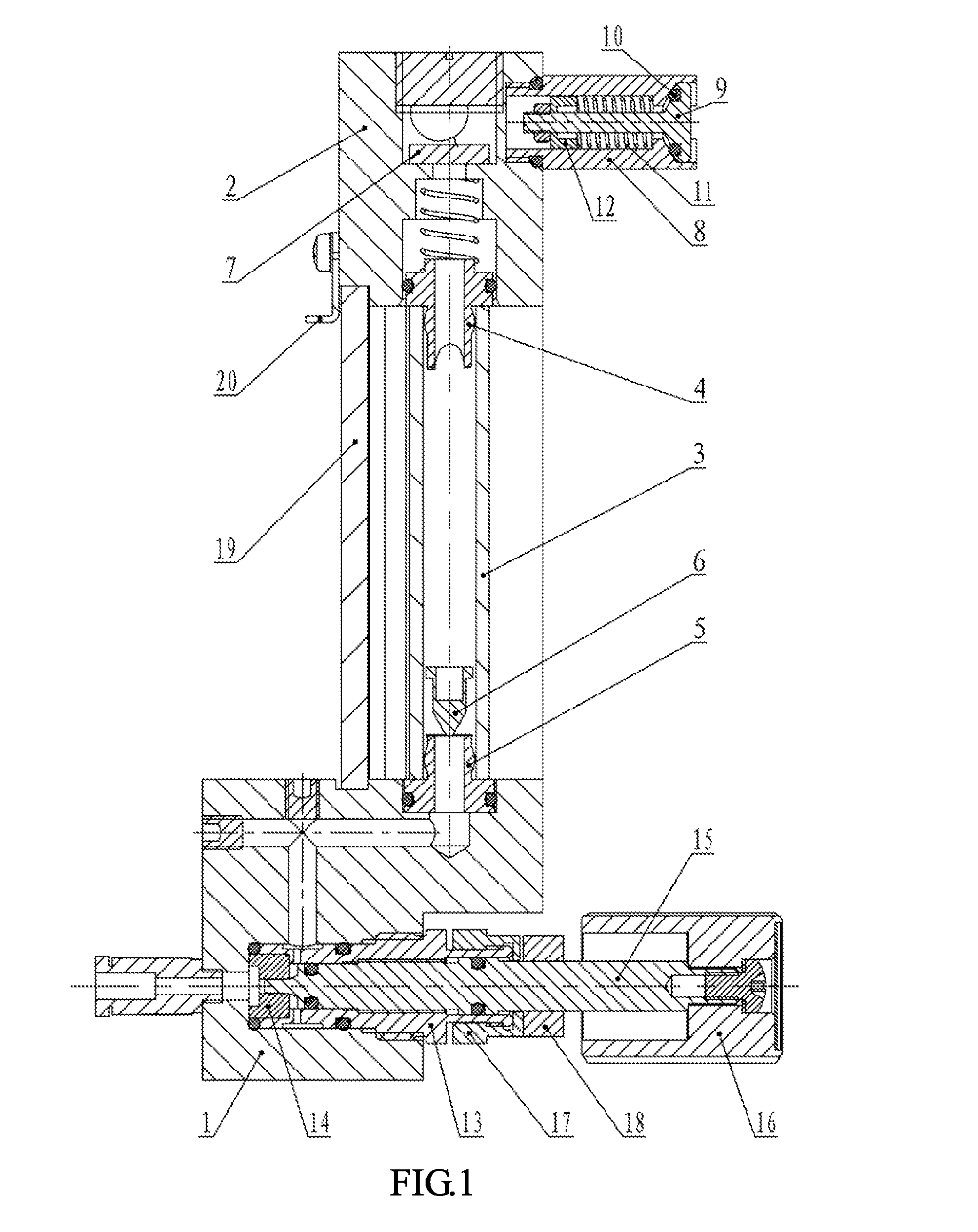
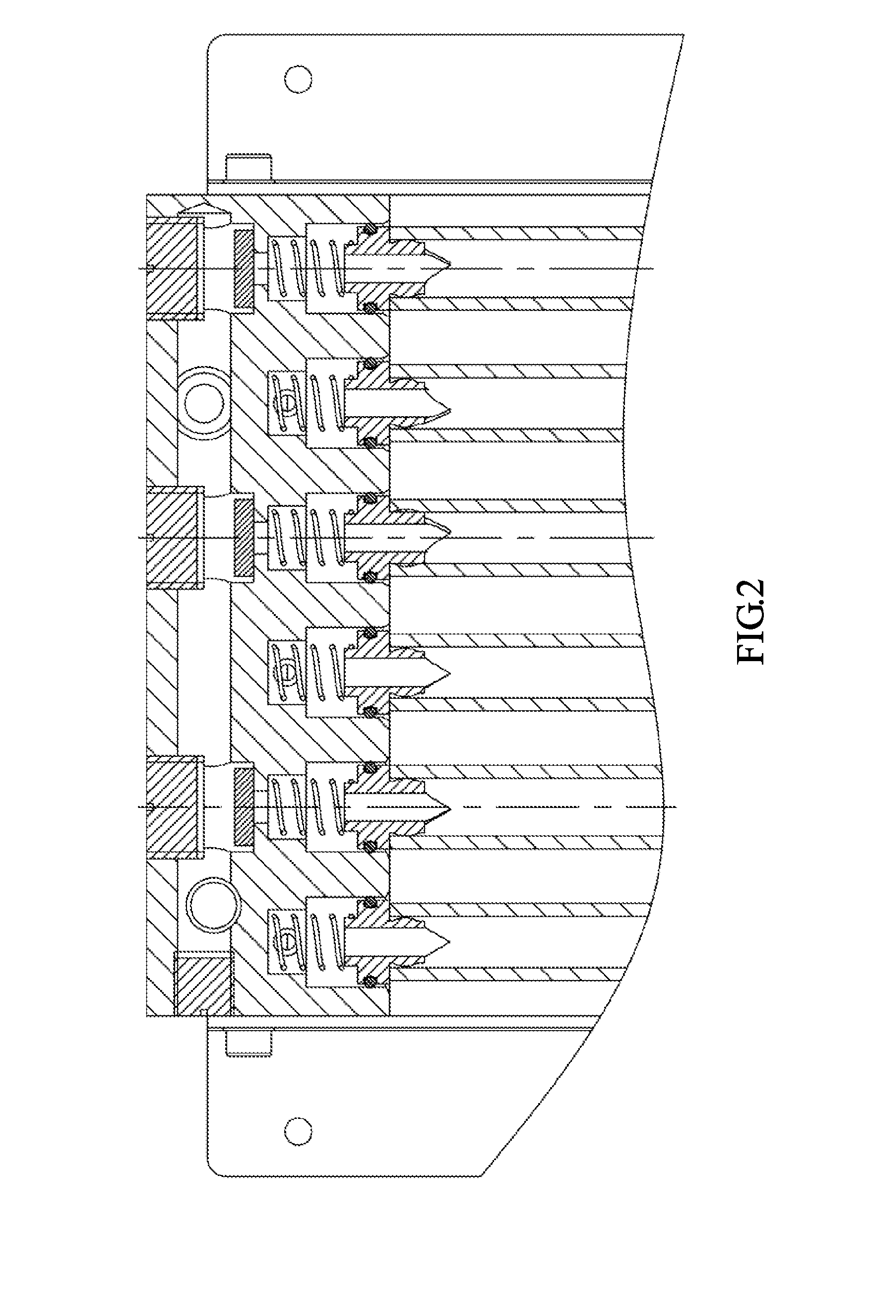
[0019]As shown in FIGS. 1-3, a flowmeter of an embodiment includes a lower valve body 1, a throttle valve assembly, a flow tube assembly, an upper valve body 2 and a pressure fluctuation suppressing assembly. The lower valve body 1 contains an air inlet, an air outlet, and an airflow passage in communication with the air inlet and the air outlet, and is also provided with a throttle valve assembly used for adjusting the open degree of the airflow passage in the lower valve body 1. The flow tube assembly includes a flow tube 3, an upper base 4, a lower base 5 and a float 6, where a ventilation hole is provided axially at the center of each of the upper base 4 and the lower base 5, and the lower base 5 is arranged at the air outlet of the lower valve body 1. A vertical airflow passage and a horizontal airflow passage are provided within the upper valve body 2, the upper base 4 is arranged at an air inlet of the vertical airflow passage in the upper valve body, the flow tube 3 is arran...


PUM


Abstract

A flowmeter comprises a lower valve body (1), a throttle assembly, a flow tube assembly, an upper valve body (2), and a pressure fluctuation suppression assembly. An air inlet, an air outlet and an air flow channel connecting the air inlet and the air outlet are arranged in the lower valve body (1); a throttle assembly for adjusting the degree of opening of the air flow channel in the lower valve body (1) is further disposed on the lower valve body (1). The flow tube assembly comprises a flow tube (3), an upper base (4), a lower base (5), and a float (6); a vent hole is provided on each of axial centers of the upper base (4) and the lower base (5); the lower base (5) is arranged at the air outlet of the lower valve body (1); a vertical air flow passage and a horizontal air flow passage are arranged in the upper valve body (2); the upper base (4) is arranged at an air inlet of the vertical air flow passage in the upper valve body (2); the flow tube (3) is disposed between the upper base (4) and the lower base (5) through two ends thereof that are respectively sleeved on protruding portions of the upper base (4) and the lower base (5); the float (6) is disposed in the flow tube (3). The pressure fluctuation suppression assembly comprises a sealing gasket (7), and the sealing gasket (7) is disposed at an air outlet of the vertical air flow passage.

Description

FIELD OF THE INVENTION[0001]The present invention relates to a flowmeter, and more particularly, to a flowmeter for an anesthesia machine.BACKGROUND OF THE INVENTION[0002]The flowmeter, as an essential part of the anesthesia machine, may be adjusted by a doctor to provide for a suitable flow of oxygen to a patient. The existing flowmeter for the anesthesia machine has the following problems that: (1) the flowmeter float beats during the normal operation of the bellows of the anesthesia machine; (2) the air within the flowmeter cannot be discharged effectively in the case of excessive air resistance at the flowmeter outlet; and (3) its structure is complex and its manufacture cost is high.SUMMARY OF THE INVENTION[0003]The aim of the invention is to provide a flowmeter, in order to solve the problems of the existing flowmeter used for an anesthesia machine, including a complex structure and a high manufacture cost, beating of the float of the flowmeter during the normal working of the...

Claims


Application Information

Patent Timeline
IPC IPC(8): A61M16/20A61M16/12A61M16/10A61M16/01
CPCA61M16/201A61M16/01A61M2016/003A61M16/1005A61M16/122G01F1/22A61M16/20A61M2205/3334A61M16/209G01F1/26
Inventor ZHENG, DIANHUI
Owner BEIJING AEONMED
Learn More