Damping force variable valve assembly and damping force variable shock absorber having the same

a technology of variable valve assembly and variable shock absorber, which is applied in the direction of shock absorbers, valve operating means/release devices, transportation and packaging, etc., can solve the problems of low or ultra-low flow rate of working fluid in the shock absorber, poor damping force characteristic of the conventional shock absorber in the section where a moving speed of a working fluid is low, and the moving speed of a working fluid is so low

Active Publication Date: 2014-09-25
HL MANDO CORP
View PDF7 Cites 13 Cited by
  • Summary
  • Abstract
  • Description
  • Claims
  • Application Information

AI Technical Summary

Benefits of technology

[0026]According to another aspect of the present invention, a damping force variable shock absorber for adjusting a damping force of the shock absorber, includes: a base shell in which a damping force variable valve assembly is attached to an outside thereof; an inner tube which is installed inside the base shell and in which a piston rod is installed movably in a length direction; a piston valve which is connected to one end of the piston rod such that an inner space of the inner tube is partitioned into a rebound chamber and a compression chamber; and a separator tube which partitions a space between the base shell and the inner tube into a low pressure chamber and a high pressure chamber. The damping force variable valve assembly may include: a spool which is movable by a magnetic force of a solenoid; a spool guide which ...

Problems solved by technology

However, in spite of many efforts to improve the performance of the damping force variable valve assembly, the conventional shock absorber has a poor damping force characteristic in a section where a moving speed of a working fluid is low.
However, ...

Method used


Image

  • Damping force variable valve assembly and damping force variable shock absorber having the same
  • Damping force variable valve assembly and damping force variable shock absorber having the same
  • Damping force variable valve assembly and damping force variable shock absorber having the same

Examples


Embodiment Construction

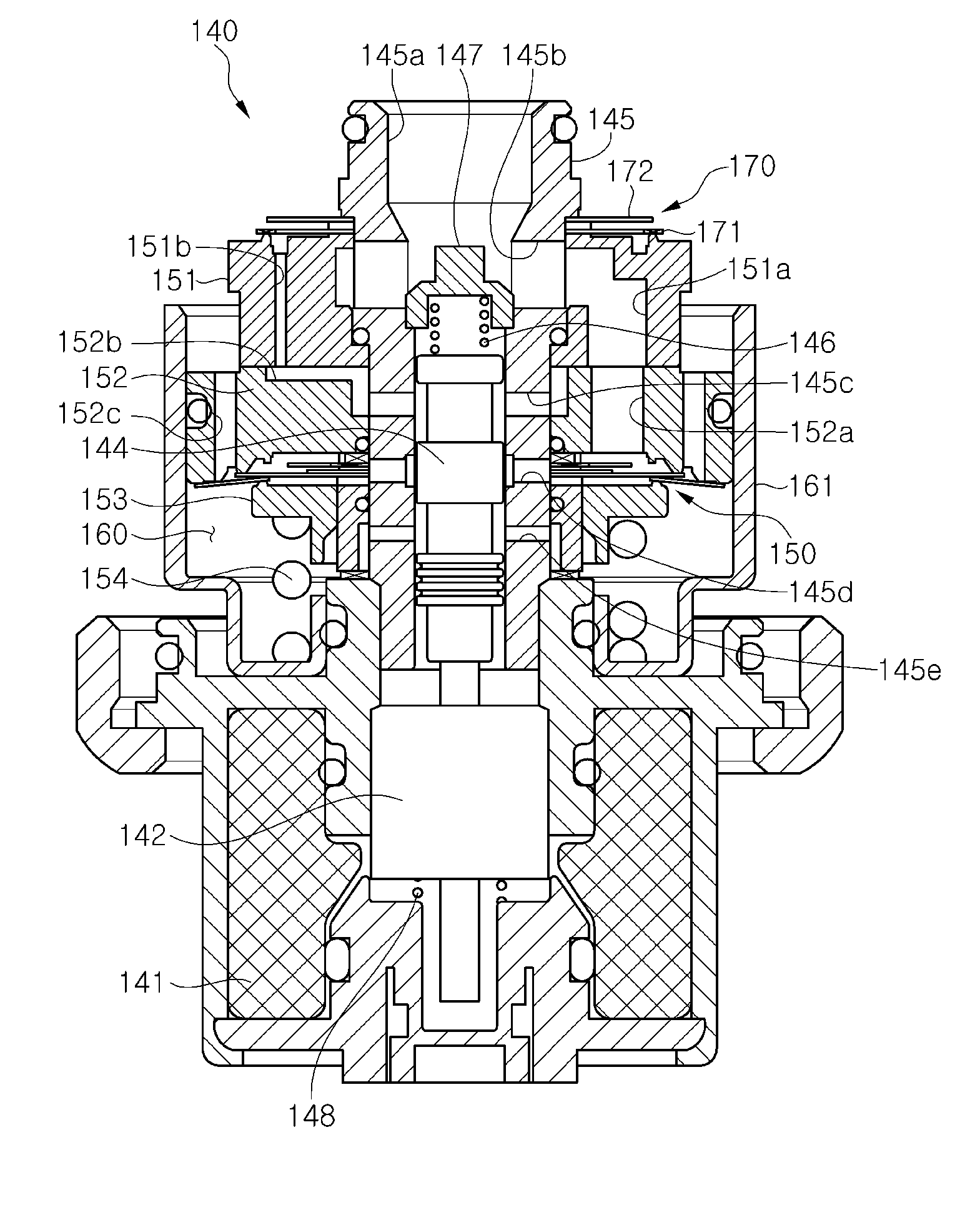
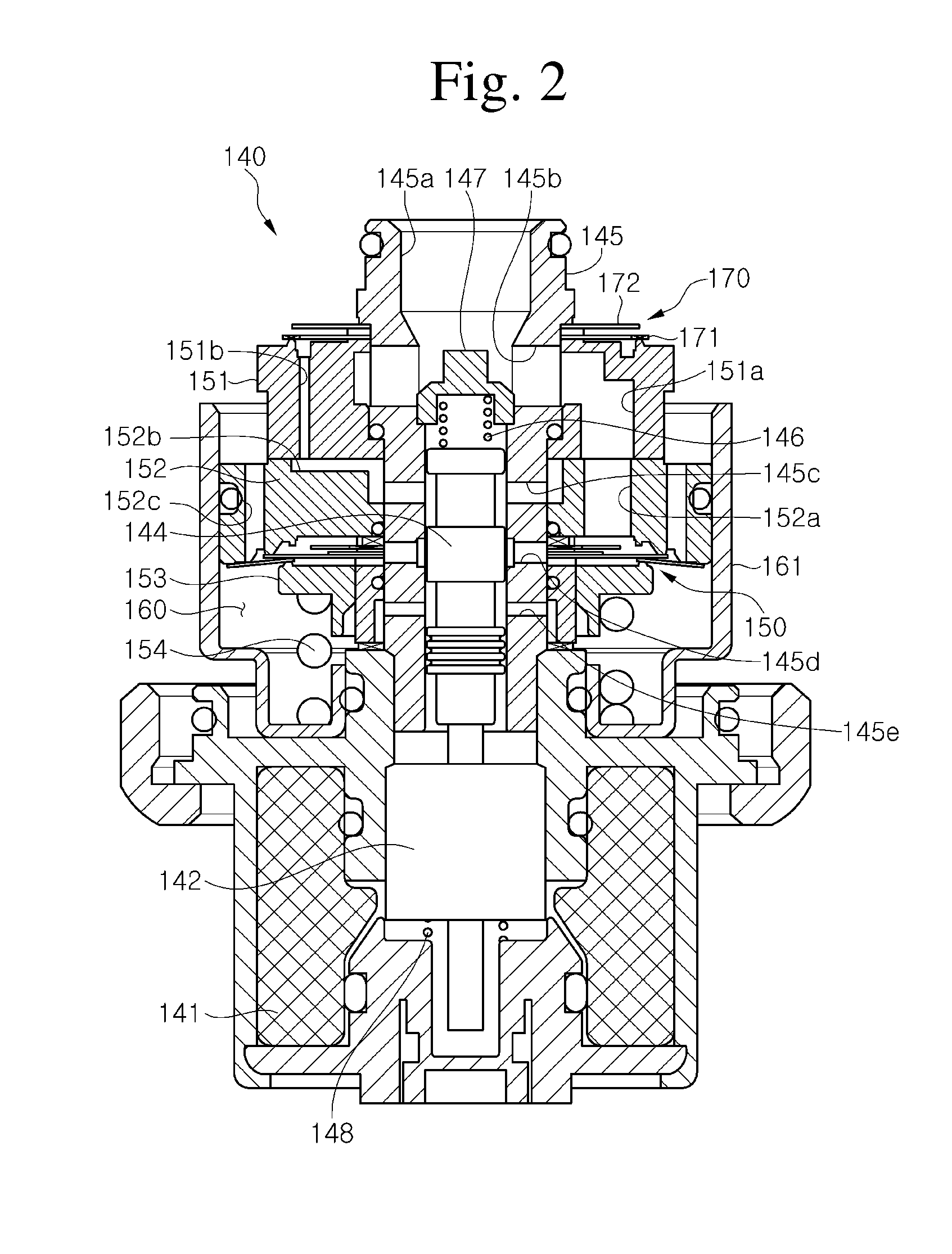
[0032]Hereinafter, a damping force variable valve assembly of a damping force variable shock absorber according to exemplary embodiments of the present invention will be described in detail with reference to the accompanying drawings. In the following description given with reference to FIGS. 2 to 5, like reference numerals as those of FIG. 1 are used to refer to like elements.

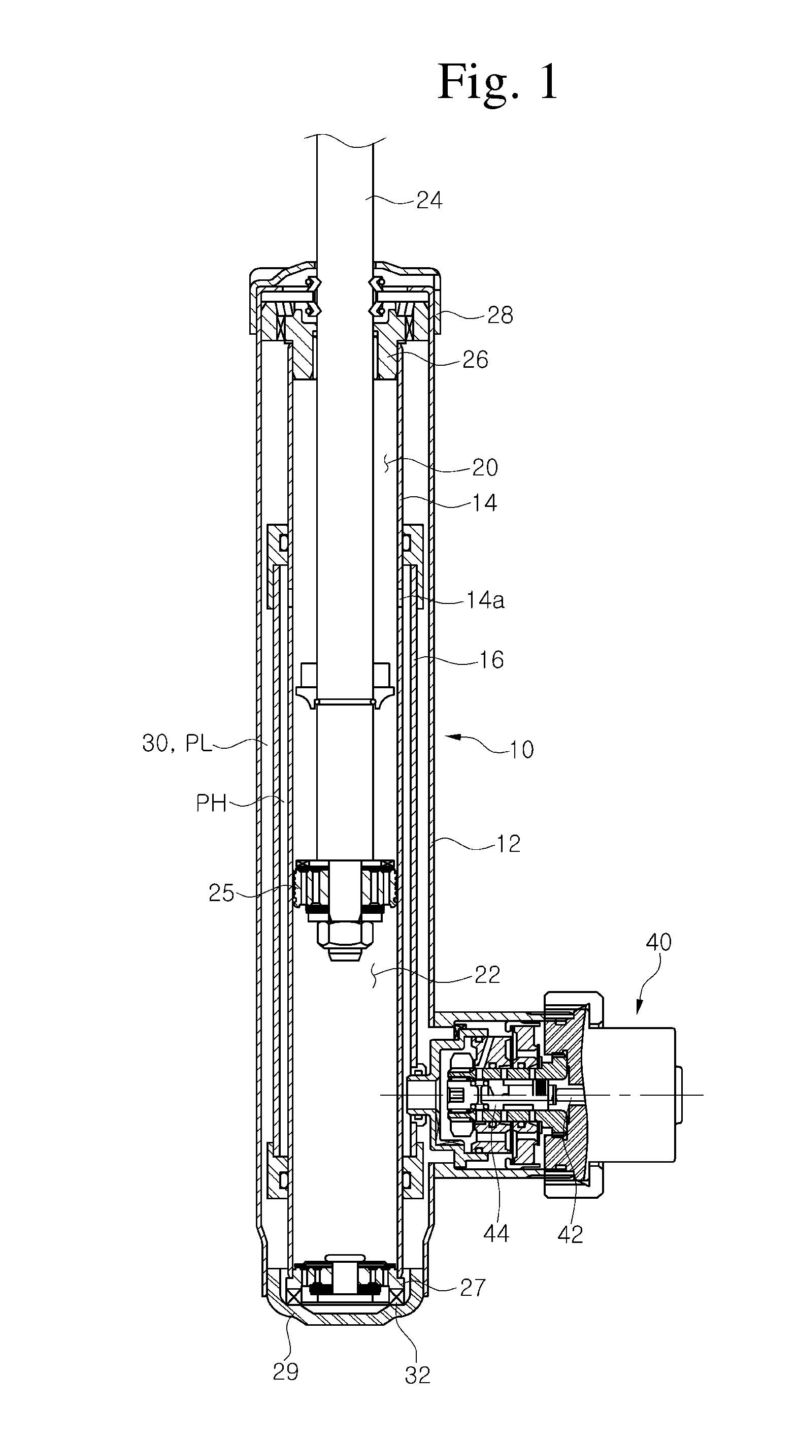
[0033]According to the present invention, the damping force variable valve assembly 140 is provided with oil passages communicating with a high pressure chamber PH and a low pressure chamber PL connected to a base shell 12 and a separator tube 16, respectively. Since a structure in which the damping force variable valve assembly 140 is connected to the base shell 12 and the separator tube 16 and communicates with the high pressure chamber PH and the low pressure chamber PL is similar to that of the related art illustrated in FIG. 1, a structure in which the damping force variable valve assembly is connected to...


PUM


Abstract

Provided are a damping force variable valve assembly with a low-speed control valve capable of controlling an ultra-low flow rate and a low flow rate when a damping force variable valve operates in a soft mode, and a damping force variable shock absorber including the damping force variable valve assembly. The damping force variable valve assembly, which is installed in a damping force variable shock absorber for adjustment of a damping force of the shock absorber, includes: a solenoid; a spool which is movable by the magnetic force of the solenoid; a spool guide which surrounds the spool; a main valve which is installed in a main passage formed in a valve body installed in the spool guide; a back pressure chamber which is provided in the rear of the main valve; a chamber forming body which forms the back pressure chamber.

Description

CROSS-REFERENCE(S) TO RELATED APPLICATION[0001]This application claims priority of Korean Patent Application No. 10-2013-0030691, filed on Mar. 22, 2013, in the Korean Intellectual Property Office, the contents of which are incorporated herein by reference in its entirety.BACKGROUND OF THE INVENTION[0002]1. Field of the Invention[0003]The present invention relates to a damping force variable valve assembly installed in a damping force variable shock absorber, and more particularly, to a damping force variable valve assembly with a low-speed control valve capable of controlling an ultra-low flow rate and a low flow rate when a damping force variable valve operates in a soft mode, and a damping force variable shock absorber including the damping force variable valve assembly.[0004]2. Description of the Related Art[0005]Generally, a shock absorber is installed in means of transportation such as an automobile or the like, and improves a ride comfort by absorbing and damping a vibration ...

Claims


Application Information

Patent Timeline
IPC IPC(8): F16F9/512
CPCF16F9/512Y10T137/87096F16F9/32F16F9/34F16K31/06
Inventor KIM, EUN JOONG
Owner HL MANDO CORP
Why Eureka
Try Eureka