Eureka AIR delivers breakthrough ideas for toughest innovation challenges, trusted by R&D personnel around the world.

Filter apparatus utilizing pressurized reverse cleaning by means of a filter drum

Inactive Publication Date: 2014-09-25
KOREA FILTER
View PDF4 Cites 6 Cited by
  • Summary
  • Abstract
  • Description
  • Claims
  • Application Information

AI Technical Summary

Benefits of technology

The present invention provides a filter apparatus with the following benefits: 1. A simple structure, reducing production costs and allowing for easy cleaning of filters. 2. A check valve for additional cleaning fluid and a cylinder for increased pressurizing force. 3. A flow rate control rod for reliable cleaning of both the upper and lower ends of the filter element.

Problems solved by technology

However, filters are reduced in efficiency under insufficient pressure.
In addition, over time, meshes of filters become clogged.
If a filter is clogged, it is necessary to clean the filter; which usually requires the interruption of the operation of an associated apparatus, thus greatly reducing the processing efficiency.
Replacing a filter with a new one also requires interrupting the operation of the associated apparatus.
Also, the replacement of the filter incurs costs, resulting in an increase in maintenance cost.
However, the amount of cleaning fluid discharged from the cylinder during a single process is limited.
Thus, the filter element may not be satisfactorily cleaned in a single cycle, whereby the cylinder may be forced to be repeatedly operated.
This increases the time it takes to complete the self-cleaning operation.

Method used


Image

  • Filter apparatus utilizing pressurized reverse cleaning by means of a filter drum
  • Filter apparatus utilizing pressurized reverse cleaning by means of a filter drum
  • Filter apparatus utilizing pressurized reverse cleaning by means of a filter drum

Examples


Embodiment Construction

[0031]Hereinafter, a preferred embodiment of the present invention will be described in detail with reference to the attached drawings. The embodiment just aims to help those with ordinary knowledge in this art more clearly understand the present invention rather than aiming to limit the bounds of the present invention. If in the specification, detailed descriptions of well-known functions or configurations would unnecessarily obfuscate the gist of the present invention, the detailed descriptions will be omitted.

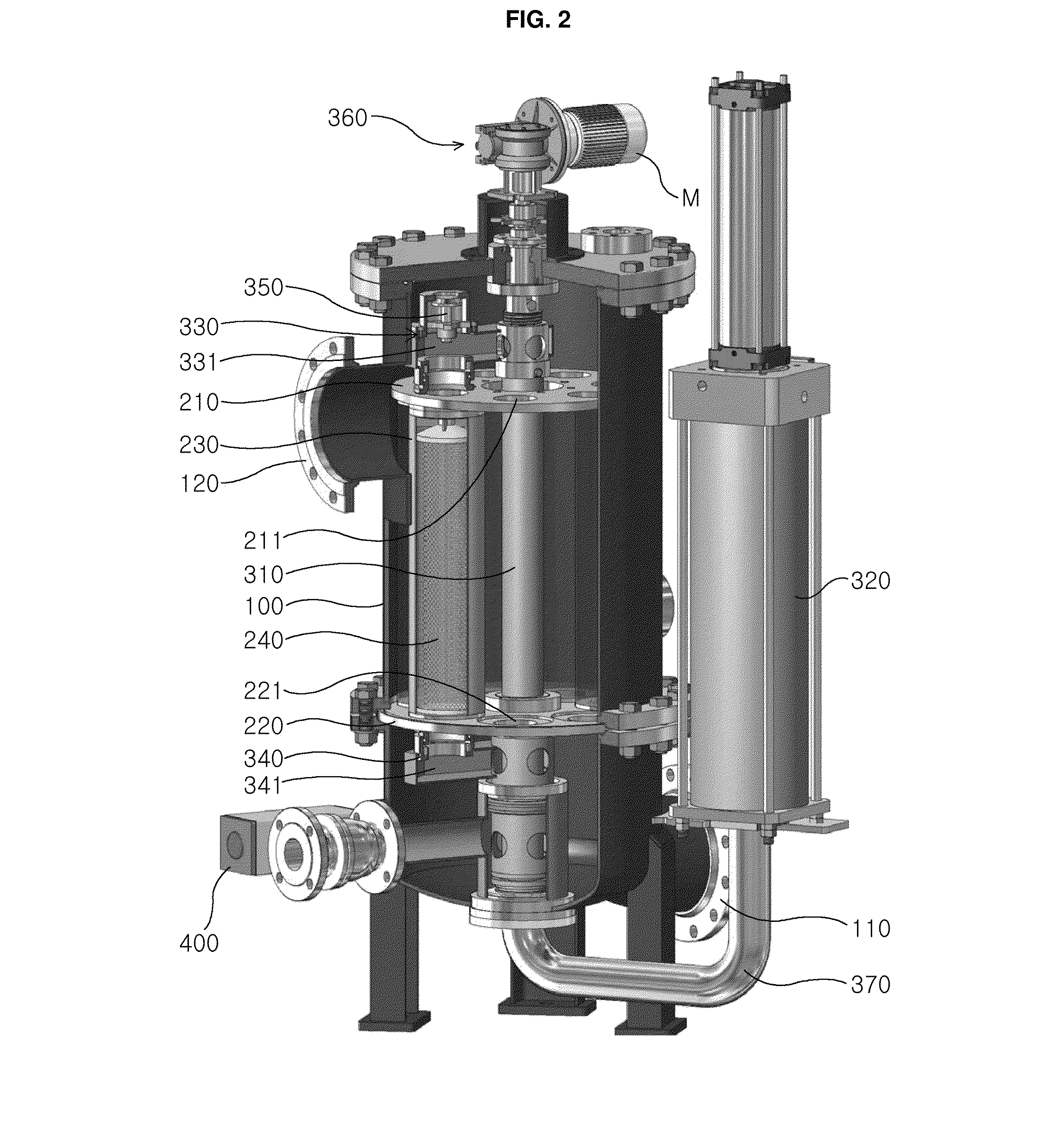
[0032]FIG. 2 is a broken perspective view illustrating a filter apparatus utilizing pressure reverse-cleaning by means of a filter drum according to a preferred embodiment of the present invention.

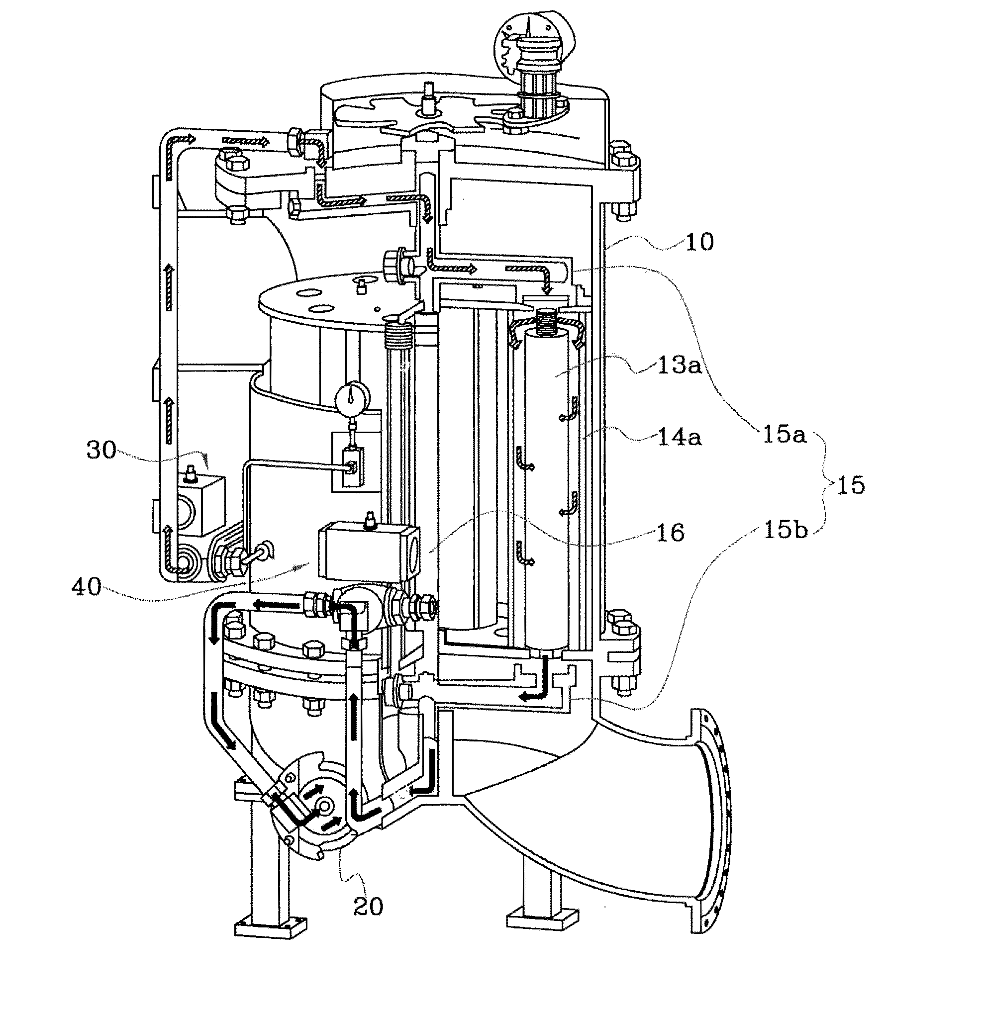
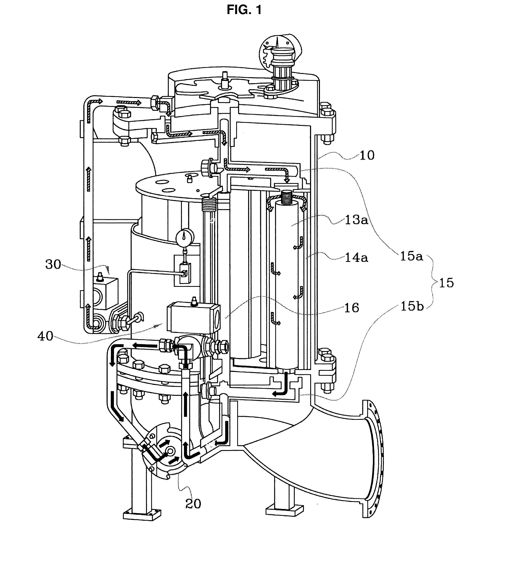
[0033]Referring to the drawing, the present invention includes a housing 100, a filtering means 200 and a filter cleaning means 300. The filter cleaning means 300 includes a check valve 350.

[0034]The housing 100 has a container shape, having a space therein. An inlet 110 through wh...


PUM

PropertyMeasurementUnit
Areaaaaaaaaaaa

Abstract

A filter apparatus utilizing pressurized reverse cleaning by a filter drum includes: a housing including an inlet and an outlet through which fluid enters and exits; a filtering means including a top plate and a bottom plate disposed apart at the top and bottom inside the housing and each forming a plurality of through holes in the circumferential direction thereof, wherein a plurality of filter drums formed in a cylindrical shape open at the top and bottom and have both ends coupled to the through holes of the top plate and the bottom plate so as to vertically communicate the plates, and wherein a filter element housed in each filter drum filters the fluid that enters; and a filter cleaning means including a supply pipe, a cylinder pressurizing the fluid and supplying the fluid to the lower portion of the supply pipe, an upper branch installed rotatably at the upper portion of the filter drum and defining a spray conduit therein , and a lower branch installed to rotate together with the upper branch and defining a discharge conduit therein.

Description

REFERENCE TO RELATED APPLICATIONS[0001]This is a continuation of pending International Patent Application PCT / KR2012 / 003207 filed on Apr. 26, 2012, which designates the United States and claims priority of Korean Patent Application No. 10-2011-0125848 filed on Nov. 29, 2011, the entire contents of which are incorporated herein by reference.FIELD OF THE INVENTION[0002]The present invention relates, in general, to self-cleaning filter apparatuses and, more particularly, to a filter apparatus in which a filter is automatically cleaned by pressurization of a cylinder.BACKGROUND OF THE INVENTION[0003]Generally, transferring fluid such as a gas or a liquid is required in most production processes as well as in a variety of industrial facilities.[0004]Foreign substances contained in fluids have great influence on the yield and performance of the production processes.[0005]Therefore, there is a need for filtering such fluids to provide high-purity fluid.[0006]However, filters are reduced in...

Claims


Application Information

Patent Timeline
IPC IPC(8): B01D29/66B01D29/52B01D29/23
CPCB01D29/668B01D29/52B01D29/23B01D29/11B01D29/62B01D29/688B01D35/12B01D2201/0453B01D2201/583
Inventor PARK, BYUNG-KEUN
Owner KOREA FILTER
Why Eureka
Eureka Blog
Learn More