
Method for detecting changes of position of shaftless spinning rotor of open-end spinning machine in cavity of active magnetic bearing and spinning unit of open-end spinning machine with active magnetic bearing for bearing shaftless spinning rotor

a technology of active magnetic bearing and shaftless spinning rotor, which is applied in the direction of open-end spinning machines, mechanical equipment, instruments, etc., can solve the problems of inability to reliably identify the position change of the spinning rotor, the inability to correct the so-called oscillation, and the cost of solution. , to achieve the effect of better detection of the position

Inactive Publication Date: 2014-09-25
RIETER CZ AS
View PDF17 Cites 6 Cited by
  • Summary
  • Abstract
  • Description
  • Claims
  • Application Information

AI Technical Summary

Benefits of technology

The patent describes an improved way to detect the position of a rotating machine part in real-time during its spinning. This solution ensures quick and accurate detection, which can be relied on for reliable results.

Problems solved by technology

In the active magnetic bearings in which the height of the spinning rotor approximates the diameter of the spinning rotor there is a problem of correctly recognizing particularly the so-called oscillations of the spinning rotor during its rotation, i.e. variations of the actual rotation axis of the spinning rotor in relation to the theoretical rotation axis of the spinning rotor.
However, in this disposition they are not capable of identifying reliably changes of the position of the spinning rotor caused by the oscillations of the spinning rotor, whereby these possible oscillations are not corrected spontaneously by the action of the magnetic forces of the permanent magnets of the active magnetic bearing.
However, this solution is costly and requires additional space for a second, parallel system of sensors, detectors and evaluation circuits.
Furthermore, due to the small length of shaftless spinning rotors and due to generally relatively small spinning units with active magnetic bearings in open-end spinning machines, this necessary additional space is not available without a substantial increase in the length of shaftless spinning rotors as well as in the external dimensions of the spinning units.

Method used


Image

  • Method for detecting changes of position of shaftless spinning rotor of open-end spinning machine in cavity of active magnetic bearing and spinning unit of open-end spinning machine with active magnetic bearing for bearing shaftless spinning rotor
  • Method for detecting changes of position of shaftless spinning rotor of open-end spinning machine in cavity of active magnetic bearing and spinning unit of open-end spinning machine with active magnetic bearing for bearing shaftless spinning rotor
  • Method for detecting changes of position of shaftless spinning rotor of open-end spinning machine in cavity of active magnetic bearing and spinning unit of open-end spinning machine with active magnetic bearing for bearing shaftless spinning rotor

Examples


Embodiment Construction

[0017]The invention will become more apparent from the following description of an example of embodiment of an active magnetic bearing with a shaftless spinning rotor for a spinning unit of an open-end spinning machine.

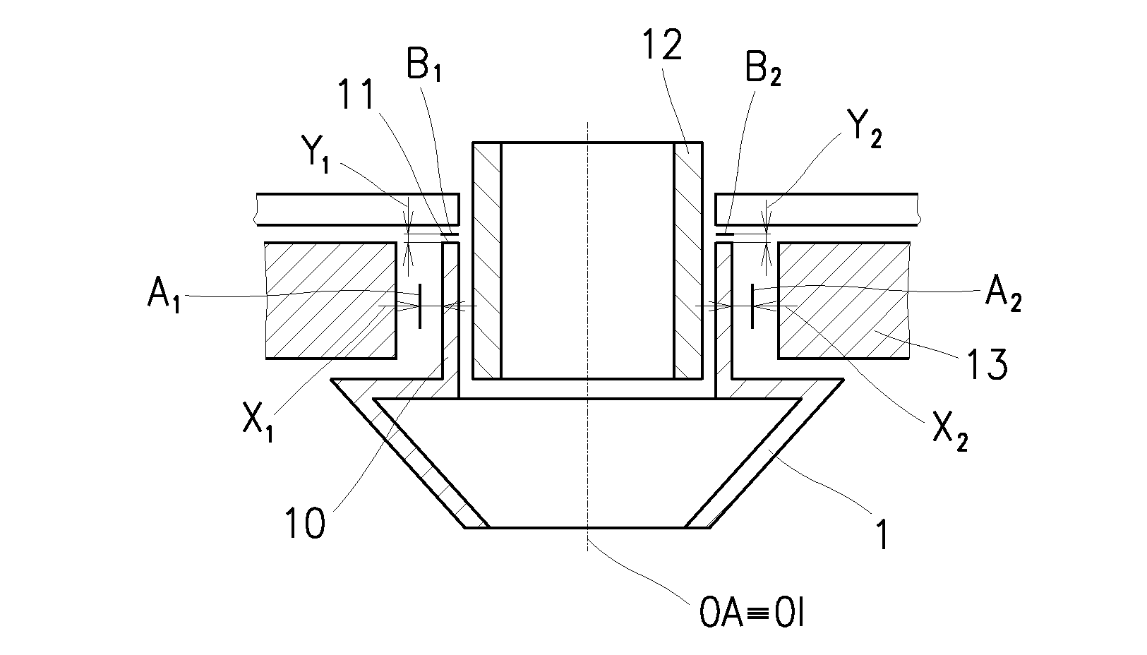
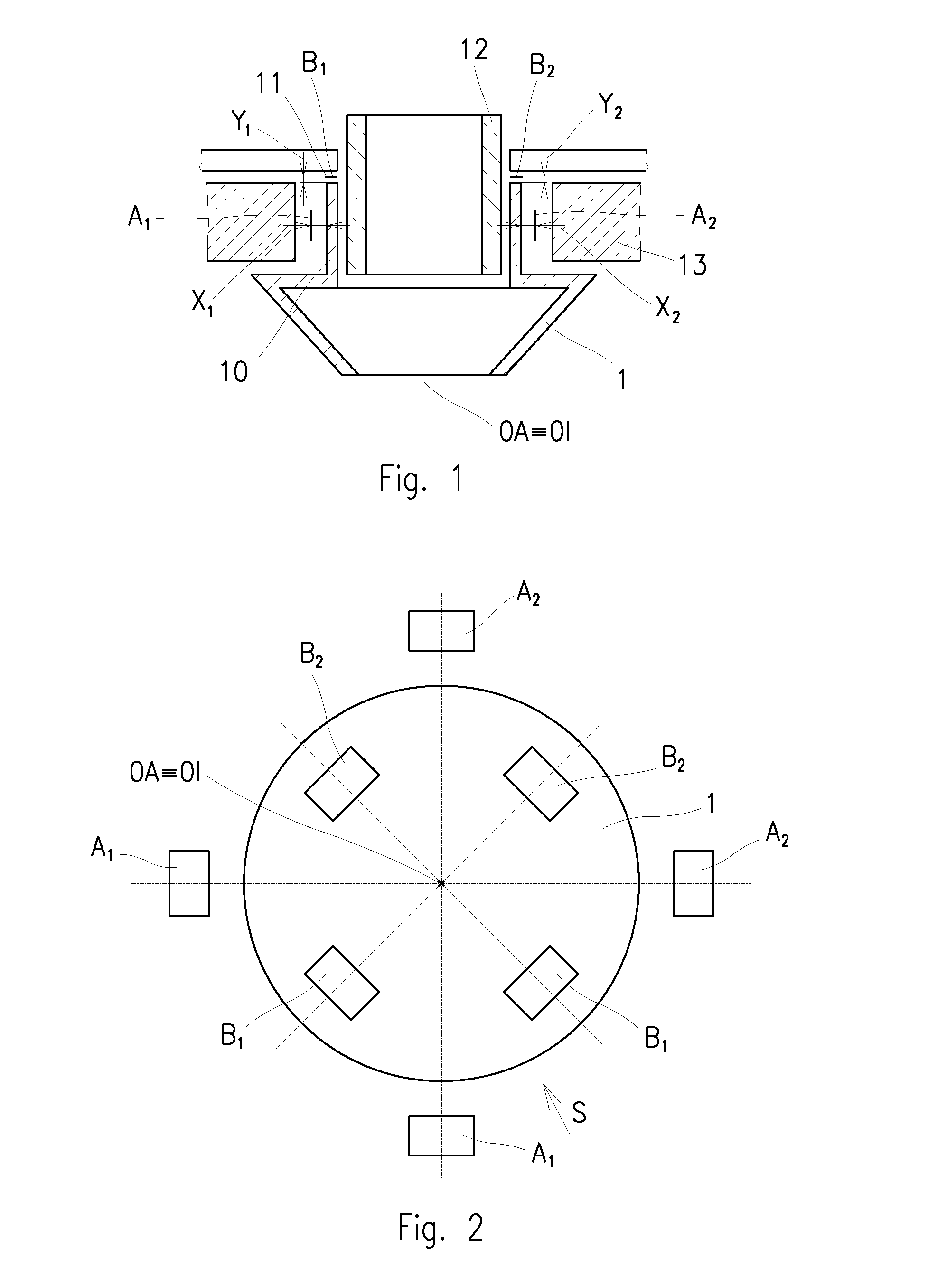
[0018]An open-end spinning machine comprises at least one row of operating units situated next to each other. Each operating unit comprises, apart from a number of other components, also a spinning unit, in which is arranged an active magnetic bearing, in which a shaftless spinning rotor 1 is rotatably mounted. The active magnetic bearing ensures maintaining the position of the spinning rotor 1 in relation to the other parts of the spinning unit by means of a controlled magnetic stabilization system 13. The drive of the spinning rotor 1 is ensured by means of a controlled electromagnetic driving system 12.

[0019]Under the position of the spinning rotor 1 we understand positioning the spinning rotor 1 in a three-dimensional coordinate system, i.e. including the current ...


PUM

PropertyMeasurementUnit
Angleaaaaaaaaaa
Magnetic fieldaaaaaaaaaa
Distanceaaaaaaaaaa

Abstract

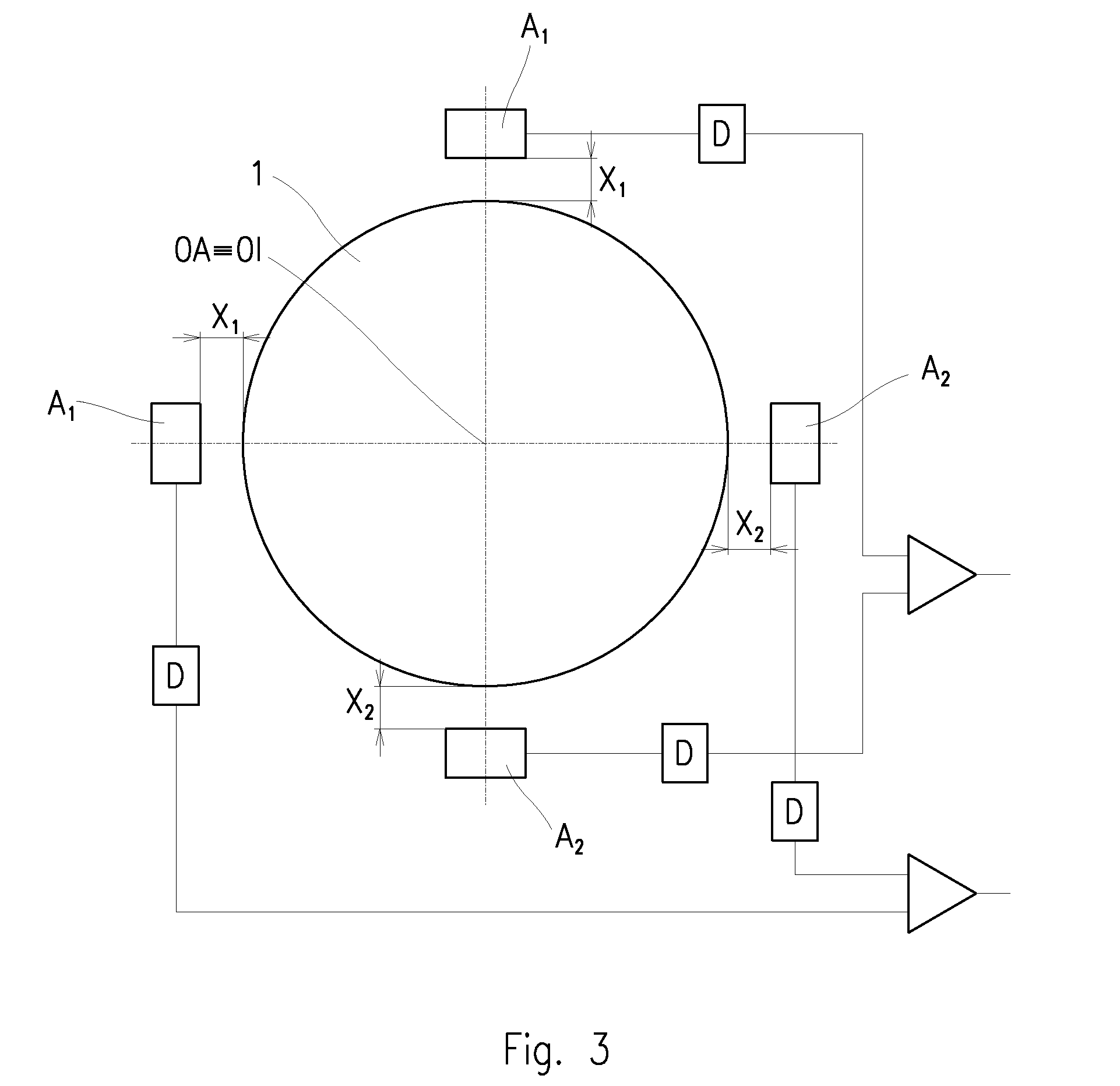
The invention relates to a method for detecting changes of position of a shaftless spinning rotor (1) of an open-end spinning machine in a cavity of an active magnetic bearing, in which the position of the spinning rotor (1) is detected by a system of sensors (A, B) and on basis of the detected changes in the position of the spinning rotor (1) is adjusted controlling of the active magnetic bearing in order to eliminate undesirable changes in the position of the spinning rotor (1) in the cavity of the active magnetic bearing. Continuously is detected radial shifting of the spinning rotor (1) and simultaneously is continuously detected inclination of the spinning rotor (1), whereupon according to the detected changes in the position of the spinning rotor (1) is determined shifting and / or inclination of the spinning rotor (1) which is used for subsequent adjustment of the controlling of position of the spinning rotor (1) in the active magnetic bearing. The invention also relates to a spinning unit of an open-end spinning machine with an active magnetic bearing for bearing a shaftless spinning rotor (1) which comprises means for creating and controlling of a magnetic field, in which the spinning rotor (1) is arranged, whereby the bearing further comprises sensors (A, B) of the position of the spinning rotor (1), the sensors (A, B) are coupled with detectors (D) of their output signals and are coupled with evaluation circuits and the evaluation circuits is connected to the control system of the active magnetic bearing. The sensors (A, B) of the position of the spinning rotor (1) are grouped into pairs, whereby two pairs of sensors (A, A1, A2) for detecting of radial shifting of the spinning rotor (1) are arranged on the opposite sides of the spinning rotor (1) against the cylindrical wall (10) of the spinning rotor (1) and at the same time two pairs of sensors (B, B1, B2) for detecting of inclination of the spinning rotor (1) are arranged on the opposite sides of the spinning rotor (1) against the wall (11) of the spinning rotor (1), which is perpendicular to the rotation axis (OA) of the spinning rotor (1).

Description

TECHNICAL FIELD[0001]The invention relates to a method for detecting changes of position of a shaftless spinning rotor of an open-end spinning machine in a cavity of an active magnetic bearing, in which the position of the spinning rotor is detected by a system of sensors and on basis of the detected changes in the position of the spinning rotor is adjusted controlling of the active magnetic bearing in order to eliminate undesirable changes in the position of the spinning rotor in the cavity of the active magnetic bearing.[0002]The invention also relates to a spinning unit of an open-end spinning machine with an active magnetic bearing for bearing a shaftless spinning rotor which comprises means for creating and controlling of a magnetic field, in which the spinning rotor is arranged, whereby the bearing further comprises sensors of the position of the spinning rotor, the sensors are coupled with detectors of their output signals and are coupled with evaluation circuits and the eval...

Claims


Application Information

Patent Timeline
IPC IPC(8): G01B7/14
CPCD01H4/44G01B7/14F16C2340/18F16C32/0446F16C32/0451D01H4/12
Inventor MORAVEC, MILANSTUSAK, MIROSLAVSLOUPENSKY, JIRI
Owner RIETER CZ AS
Learn More