
Extremely high frequency (EHF) distributed antenna systems, and related components and methods

a distributed antenna and high frequency technology, applied in multiplex communication, wireless communication, site diversity, etc., can solve the problems of substantial degradation of video quality, inability of wlan-based technology to provide sufficient bandwidth for expected demand, etc., to achieve more data intensive signals, increase bandwidth to digital data services, and increase bandwidth

Active Publication Date: 2014-09-25
CORNING OPTICAL COMM LLC
View PDF5 Cites 31 Cited by
  • Summary
  • Abstract
  • Description
  • Claims
  • Application Information

AI Technical Summary

Benefits of technology

This patent describes a system that can provide high-speed internet to mobile devices. The system uses a special frequency called EHF, which allows for the transmission of large amounts of data without affecting quality. The system includes a distributed antenna system, which can be placed in buildings or other facilities to deliver internet to clients. Overall, this technology can provide fast, reliable internet to mobile users in a variety of settings.

Problems solved by technology

Concurrently, some wireless customers use their wireless devices in areas that are poorly served by conventional cellular networks such as inside certain buildings or areas where there is little cellular coverage.
However, WiFi and WLAN-based technology may not be able to provide sufficient bandwidth for expected demand, especially as high definition (HD) video becomes more prevalent.
As an example, people want to upload or download HD video on their mobile devices and current standards do not allow this without substantial degradation to the quality of the video.

Method used


Image

  • Extremely high frequency (EHF) distributed antenna systems, and related components and methods
  • Extremely high frequency (EHF) distributed antenna systems, and related components and methods
  • Extremely high frequency (EHF) distributed antenna systems, and related components and methods

Examples


Embodiment Construction

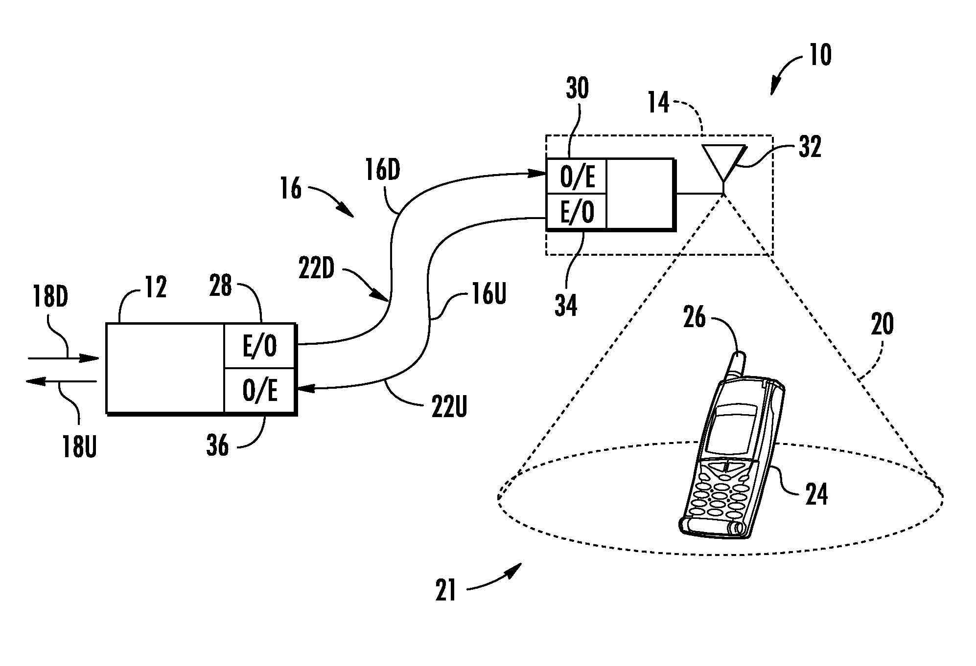
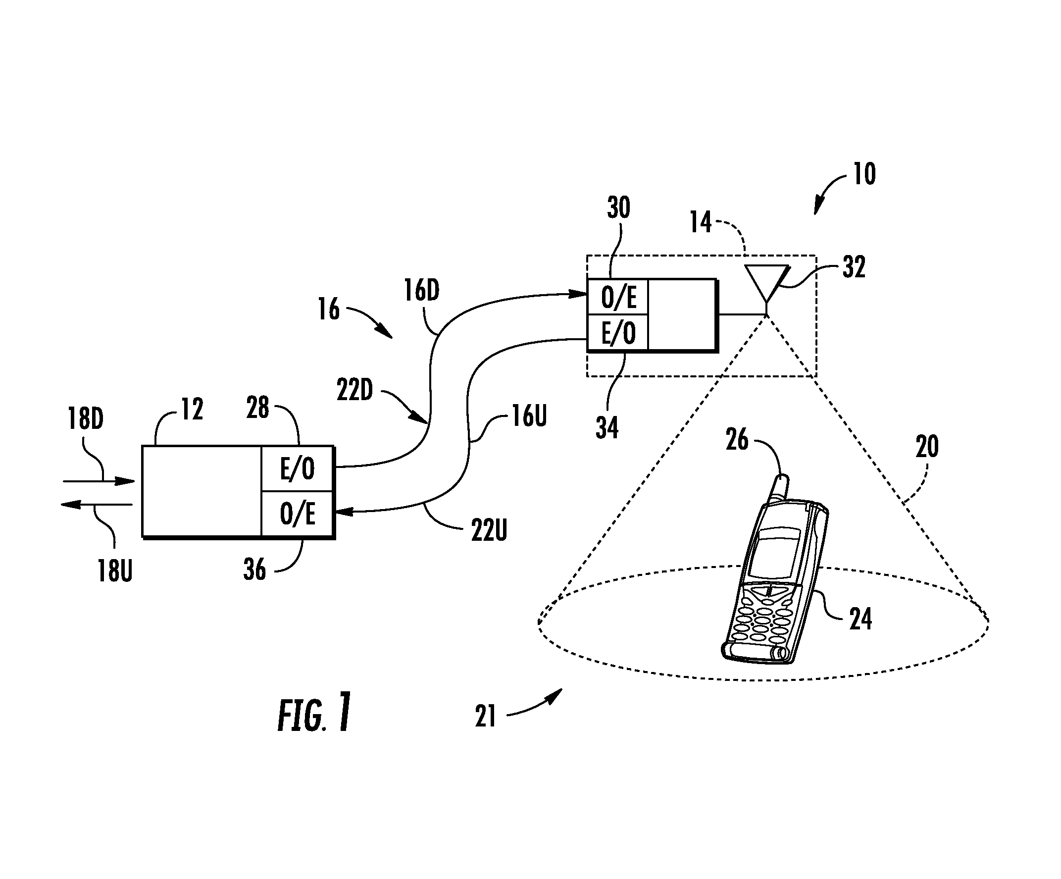
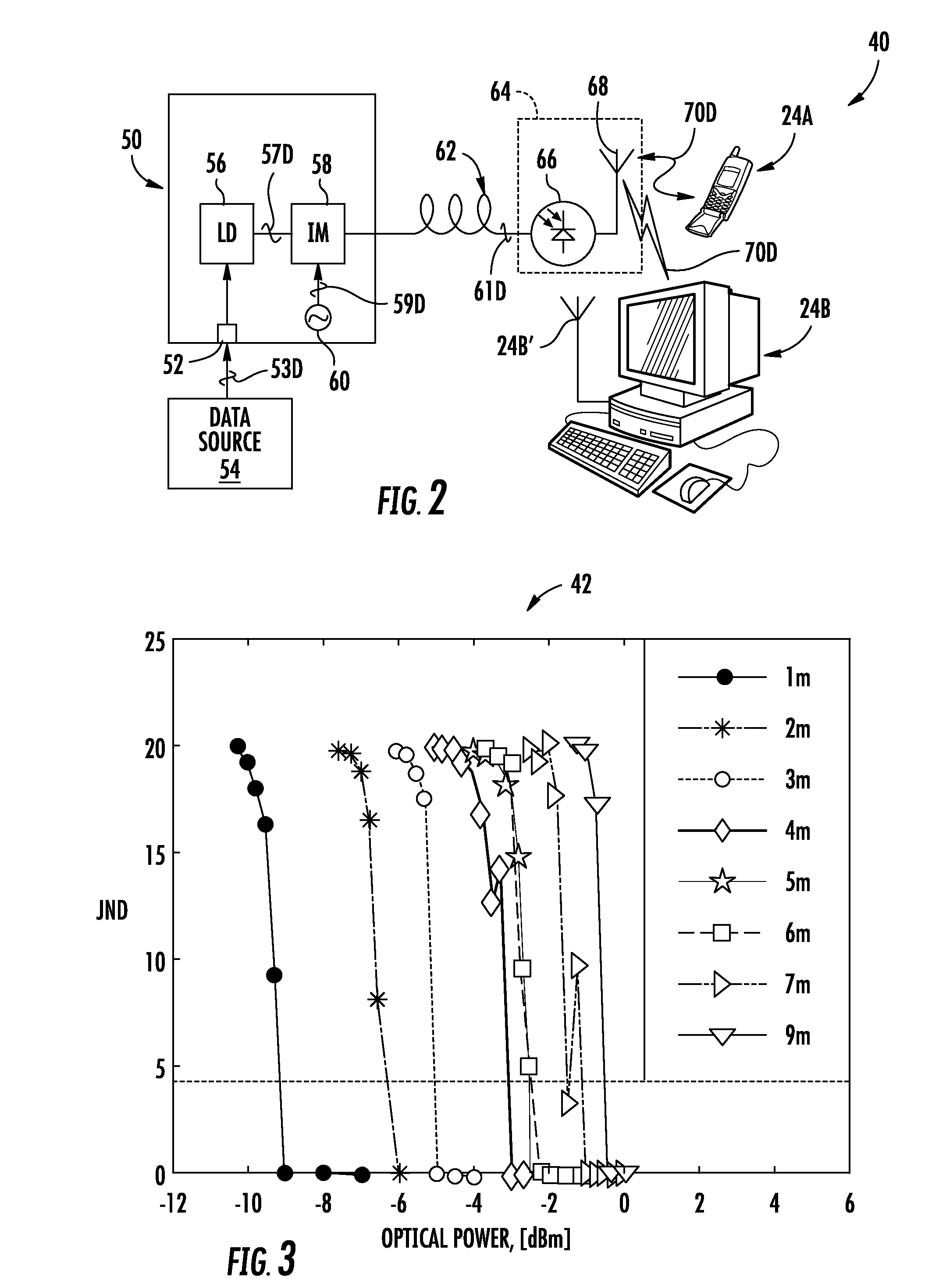
[0007]Embodiments disclosed in the detailed description include extremely high frequency (EHF) (i.e., 30-300 GHz), distributed antenna systems, and related components, and methods. The systems disclosed herein can support provision of digital data services to wireless clients. The use of the EHF band allows for the use of channels having a higher bandwidth, which in turn allows more data intensive signals to be communicated without substantial degradation to the quality of the video. As a non-limiting example, the distributed antenna systems disclosed herein may operate at an EHF of approximately 60 GHz with approximately 7 GHz bandwidth channels to provide greater bandwidth to digital data services. The distributed antenna systems disclosed herein may be well suited to be deployed in an indoor building or other facility for delivering of digital data services.

[0008]In this regard, in one embodiment, a base unit for distributing EHF modulated data signals to at least one remote ante...


PUM


Abstract

Extremely High Frequency (EHF) distributed antenna systems and related components and methods are disclosed. In one embodiment, a base unit for distributing EHF modulated data signals to a RAU(s) is provided. The base unit includes a downlink data source input configured to receive downlink electrical data signal(s) from a data source. The base unit also includes an E-O converter configured to convert downlink electrical data signal(s) into downlink optical data signal(s). The base unit also includes an oscillator configured to generate an electrical carrier signal at a center frequency in the EHF band. The base unit also includes a modulator configured to combine the downlink optical data signal(s) with the electrical carrier signal to form downlink modulated optical signal(s) comprising a downlink optical data signal(s) modulated at the center frequency of the electrical carrier signal. The modulator is further configured to send the downlink modulated optical signal to the RAU(s).

Description

RELATED APPLICATIONS[0001]This application claims the benefit of priority under 35 U.S.C. §365 of International Patent Application No. PCT / US11 / 64428 filed on Dec. 12, 2011 designating the United States of America the content of which is incorporated herein by reference in its entirety.BACKGROUND[0002]1. Field of the Disclosure[0003]The technology of the present disclosure relates to distribution of radio-frequency (RF) communications signals in distributed antenna system.[0004]2. Technical Background[0005]Wireless customers are demanding digital data services such as streaming video signals. Concurrently, some wireless customers use their wireless devices in areas that are poorly served by conventional cellular networks such as inside certain buildings or areas where there is little cellular coverage. One response to the intersection of these two concerns has been the use of distributed antenna systems, which are especially effective at providing wireless digital data services with...

Claims


Application Information

Patent Timeline
Patent Type & Authority Applications(United States)
IPC IPC(8): H04B10/2575
CPCH04B10/25752H04B10/25759H04B7/022H04B10/25751H04J14/0298H04Q11/0005H04Q2011/0016H04Q2011/0035H04Q2011/0037H04W84/12
Inventor GEORGE, JACOBNG'OMA, ANTHONYRUFFIN, ALRANZO BOHSAUER, MICHAEL
Owner CORNING OPTICAL COMM LLC
Learn More