Terminal fitting

a technology of fittings and terminals, applied in the direction of coupling contact members, coupling device connections, electrical devices, etc., can solve the problems of preventing smooth deformation of the contact main body and causing the support point to deform sufficiently, so as to achieve the effect of suppressing the resistance of the male tab to the connecting portion

Active Publication Date: 2014-09-25
SUMITOMO WIRING SYST LTD
View PDF14 Cites 15 Cited by
  • Summary
  • Abstract
  • Description
  • Claims
  • Application Information

AI Technical Summary

Benefits of technology

[0012]The supporting point may be on the front end part of the resilient contact portion and may be before the rear end of the part to be locked by the lock. Thus, insertion resistance of the male tab into the connecting portion can be suppressed.

Problems solved by technology

Caulking the receiving portions to the connecting portion could shift the receiving portions toward the contact main body, thereby narrowing the slits, and could cause the supporting point to deform sufficiently to impede smooth deformation of the contact main body.

Method used


Image

  • Terminal fitting
  • Terminal fitting
  • Terminal fitting

Examples


Embodiment Construction

[0032]A first embodiment of the invention is described with reference to FIGS. 1 to 16. A terminal fitting 10 of this embodiment is made of an electrically conductive metal plate material and is long and is narrow in a front-back direction. As shown in FIG. 13, the terminal fitting 10 is inserted into a cavity 61 of a connector housing 60 and is connected electrically to a male tab 90 of a mating connector, as shown in FIG. 15, as the housing 60 is connected to an unillustrated housing of the mating connector.

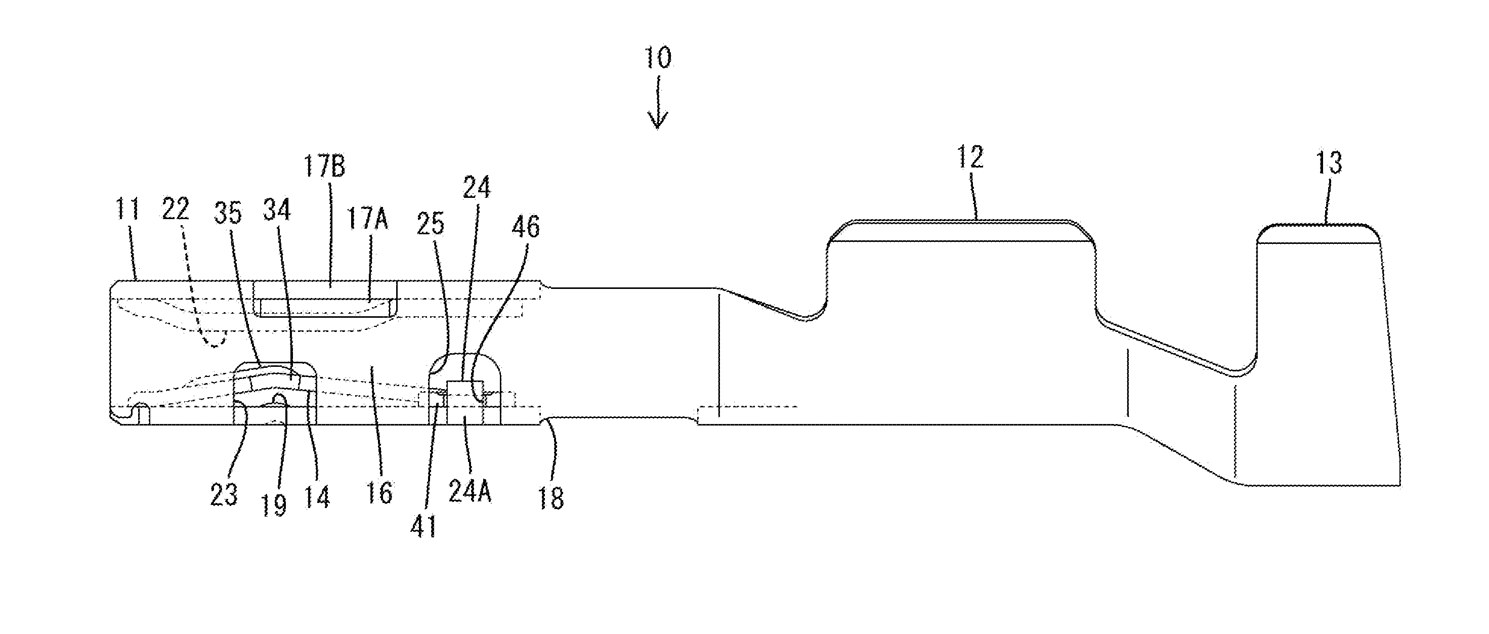
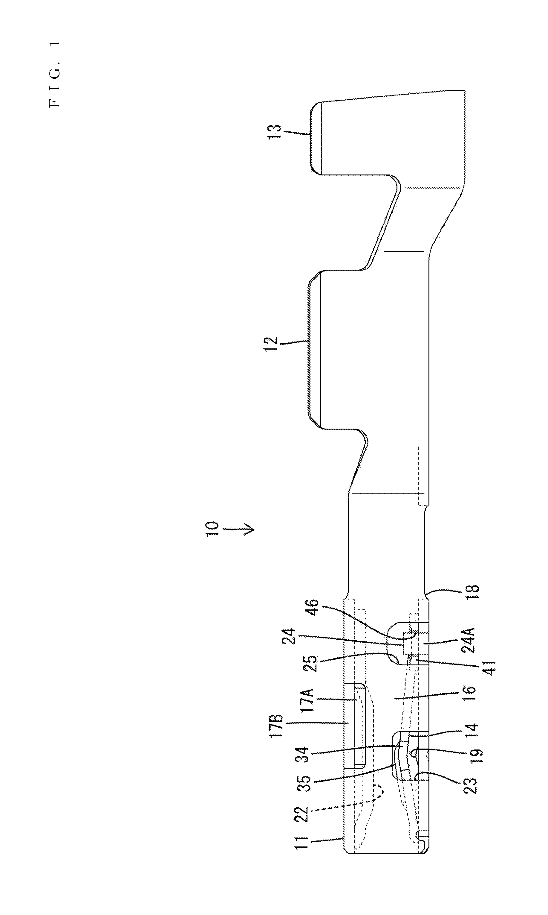
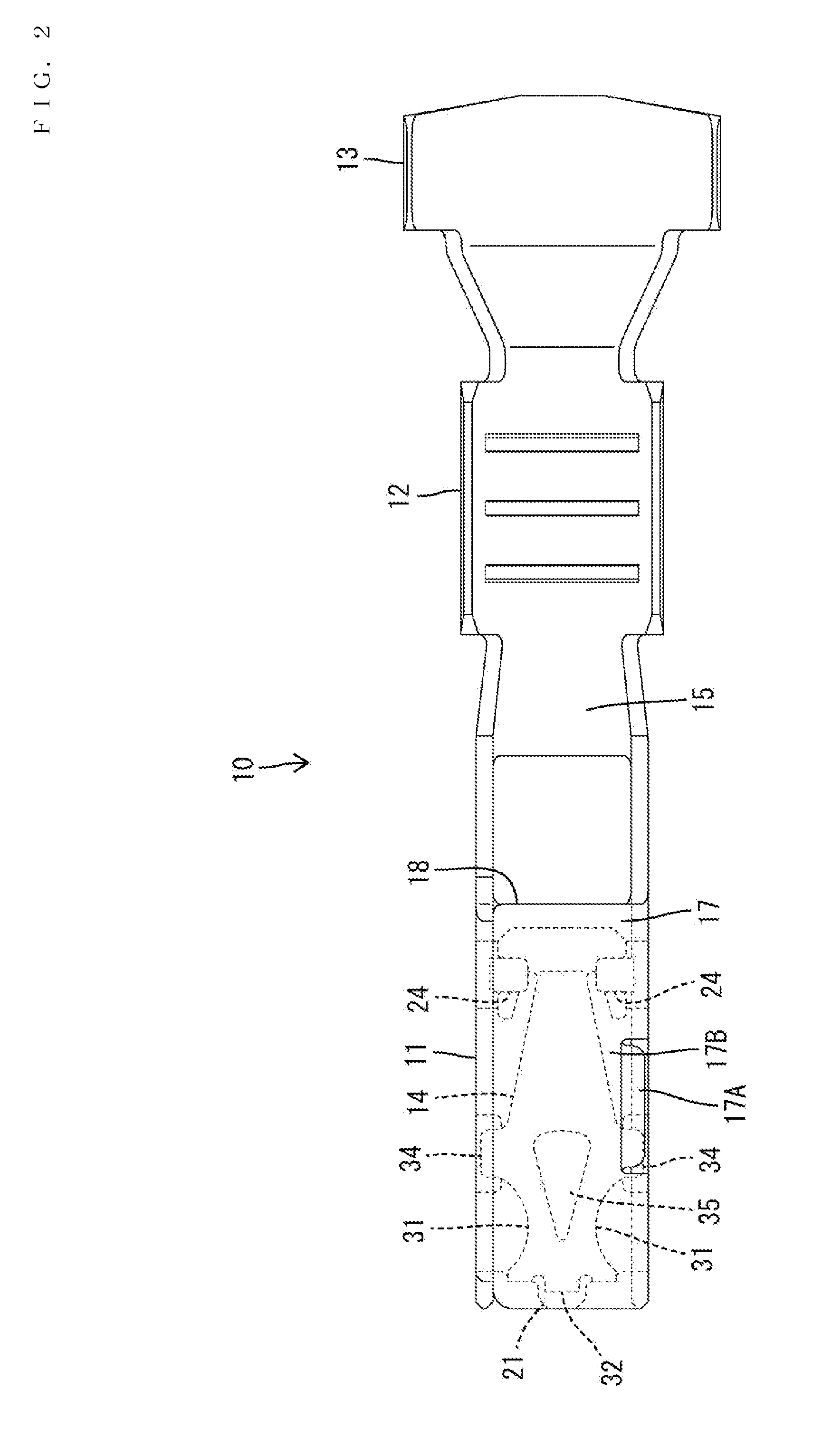
[0033]The terminal fitting 10 is shown in FIGS. 1 to 3 and includes a tubular connecting portion 11, a wire barrel 12 behind the connecting portion 11 and an insulation barrel 13 behind the wire barrel 12. A resilient contact 14 in the form of a plate is provided separately from the connecting portion 11 and is arranged in the connecting portion 11. The resilient contact 14 is made of copper alloy with high springiness and is formed of a material different from the connecting p...


PUM


Abstract

A terminal fitting (10) includes a tubular connecting portion (11) into which a male tab (90) is to be inserted. A plate-shaped resiliently deflectable contact (14) is formed separately from the connecting portion (11) and extends in a front-back direction in the connecting portion (11) for contacting the male tab (90) inserted into the connecting portion (11). The connecting portion (11) includes locks (24) for locking the resilient contact (14) to the connecting portion (11). A support (42) as a deflection supporting point of the resilient contact (14) is provided on a rear end of the resilient contact portion (14). The support (42) is located behind the front ends of receiving portions (41) of the resilient contact (14) to be locked by the locks (24).

Description

BACKGROUND[0001]1. Field of the Invention[0002]The invention relates to a terminal fitting.[0003]2. Description of the Related Art[0004]U.S. Pat. No. 6,171,155 discloses a terminal fitting that has a tubular connecting portion with a front end. A plate-shaped resiliently deflectable contact is formed separately from the connecting portion and extends in a front-back direction in the connecting portion. A tab of a mating male terminal fitting is inserted into the connecting portion from the front and contacts the resilient contact to connect the terminal fittings electrically.[0005]The connecting portion has a rear locking piece that is cut and bent from the bottom wall and shaped to lock the rear end part of the resilient contact portion from behind. Thus, a deflection support of the resilient contact is set before the rear locking piece.[0006]The longitudinal length of a spring area of the resilient contact before the deflection support needs to be sufficiently long to exhibit a sa...

Claims


Application Information

Patent Timeline
Patent Type & Authority Applications(United States)
IPC IPC(8): H01R13/187
CPCH01R13/187H01R13/113
Inventor TSUJI, TAKESHITANIGAWA, NORIHIKONORO, YUTAKAMITSUI, SHOHEI
Owner SUMITOMO WIRING SYST LTD
Why Eureka
Try Eureka