Method of adjusting profile of a polishing member used in a polishing apparatus, and polishing apparatus

a polishing member and profile adjustment technology, applied in the direction of manufacturing tools, lapping machines, abrasive surface conditioning devices, etc., can solve the problem of not getting the intended profile of the polishing member, and achieve the effect of accurately achieving the target profil

Active Publication Date: 2014-09-25
EBARA CORP
View PDF12 Cites 17 Cited by
  • Summary
  • Abstract
  • Description
  • Claims
  • Application Information

AI Technical Summary

Benefits of technology

[0011]The present invention has been made in order to solve the above issues. It is therefore an object of the present invention to provide a method of adjusting a profile of a polishing member which can achieve a target profile of a polishing member.
[0031]According to the present invention, the current profile of the polishing member is produced from the measured values of the surface height of the polishing member which has been dressed by the dresser, and the moving speeds of the dresser on the polishing member are corrected based on the difference between the target profile and the current profile. By oscillating the dresser at the moving speeds corrected in this manner, the target profile can be accurately achieved.

Problems solved by technology

However, in the conventional dressing method, an intended profile of the polishing member may not be obtained.

Method used


Image

  • Method of adjusting profile of a polishing member used in a polishing apparatus, and polishing apparatus
  • Method of adjusting profile of a polishing member used in a polishing apparatus, and polishing apparatus
  • Method of adjusting profile of a polishing member used in a polishing apparatus, and polishing apparatus

Examples


Embodiment Construction

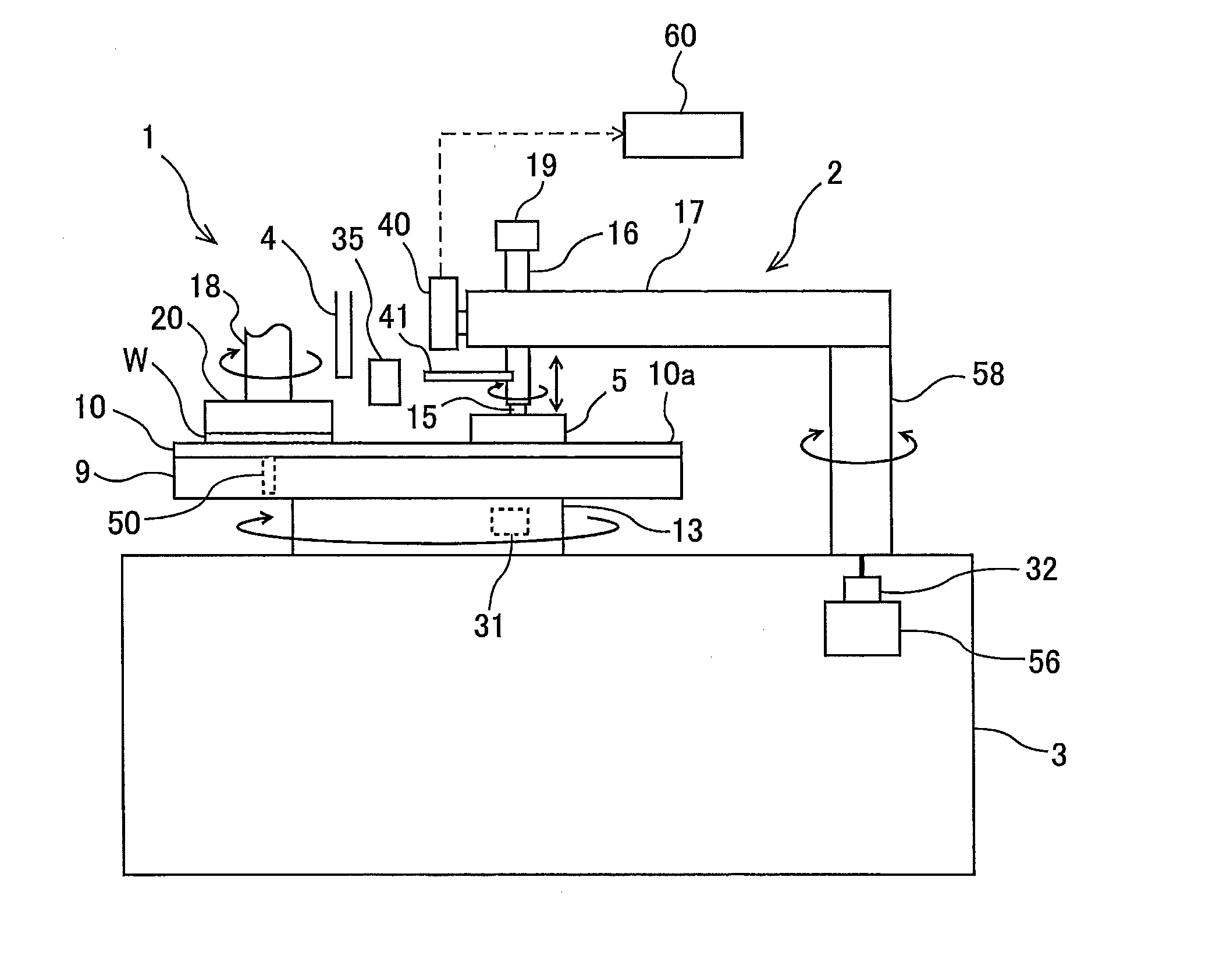
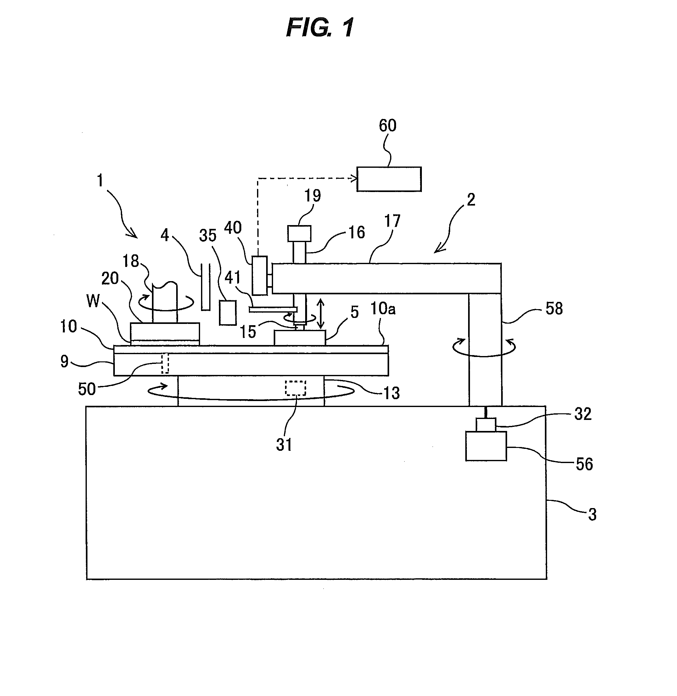
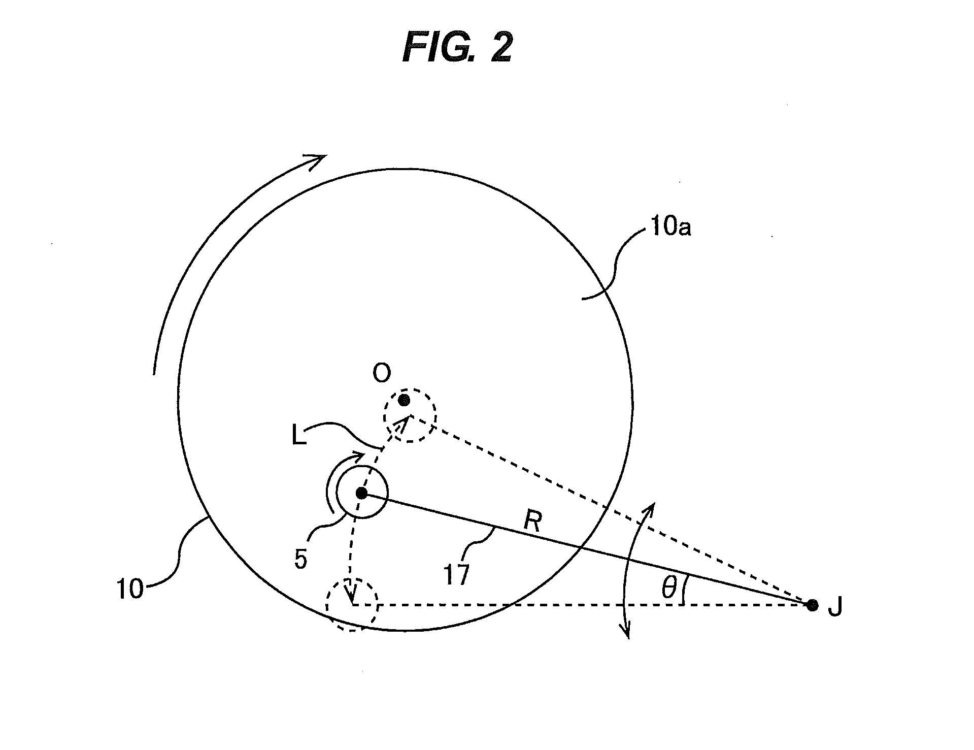
[0039]Embodiments according to the present invention will be explained with reference to the drawings. FIG. 1 is a schematic view showing a polishing apparatus for polishing a substrate, such as a wafer. As shown in FIG. 1, the polishing apparatus includes a polishing table 9 configured to hold a polishing pad (or a polishing member) 10, a polishing unit 1 configured to polish a wafer W, a polishing liquid supply nozzle 4 configured to supply a polishing liquid onto the polishing pad 10, and a dressing unit 2 configured to condition (or dress) the polishing pad 10 which is used to polish the wafer W. The polishing unit 1 and the dressing unit 2 are provided on a base 3.

[0040]The polishing unit 1 includes a top ring (or a substrate holder) 20 coupled to a lower end of a top ring shaft 18. The top ring 20 is constructed so as to hold the wafer W on its lower surface by vacuum suction. The top ring shaft 18 is rotated by a motor (not shown in the drawing), and the top ring 20 and the w...


PUM

PropertyMeasurementUnit
cutting rate ratioaaaaaaaaaa
timeaaaaaaaaaa

Abstract

The method includes the steps of measuring a surface height of a polishing member 10 at each of plural oscillation sections Z1 to Z5 which are defined in advance on the polishing member 10 along an oscillation direction of a dresser 5; calculating a difference between a current profile obtained from measured values of the surface height and a target profile of the polishing member 10; and correcting moving speeds of the dresser 5 in the plural oscillation sections Z1 to Z5 so as to eliminate the difference.

Description

CROSS REFERENCE TO RELATED APPLICATION[0001]This document claims priority to Japanese Patent Application No. 2013-034419 filed Feb. 25, 2013, the entire contents of which are hereby incorporated by reference.BACKGROUND OF THE INVENTION[0002]1. Field of the Invention[0003]The present invention relates to a method of adjusting a profile of a polishing member used in a polishing apparatus for polishing a substrate, such as a wafer.[0004]The present invention further relates to a polishing apparatus for polishing a substrate.[0005]2. Description of the Related Art[0006]As a more highly integrated structure of a semiconductor device has recently been developed, interconnects of a circuit become finer and dimensions of the integrated device decrease. Thus, it becomes necessary to polish a wafer having films (e.g., metal film) on its surface to planarize the surface of the wafer. One example of the planarization technique is a polishing process performed by a chemical-mechanical polishing ...

Claims


Application Information

Patent Timeline
Patent Type & Authority Applications(United States)
IPC IPC(8): B24B53/017B24B37/005
CPCB24B37/005B24B53/017H01L21/304
Inventor SHIMANO, TAKAHIROTANIKAWA, MUTSUMIMATSUO, HISANORIYAMAGUCHI, KUNIAKIWATANABE, KATSUHIDE
Owner EBARA CORP
Why Eureka
Try Eureka