Isolator system

a technology of isolation system and isolation chamber, which is applied in the direction of manufacturing tools, lighting and heating apparatus, heating types, etc., can solve the problems of substantial investment and maintenance costs of the facility

Active Publication Date: 2014-10-02
SHIBUYA IND CO LTD
View PDF20 Cites 66 Cited by
  • Summary
  • Abstract
  • Description
  • Claims
  • Application Information

AI Technical Summary

Benefits of technology

[0011]Here, the isolator, the pass box, and the clean booth are arranged in the building. After the interiors of the sterile operation area in the isolator and the clean booth are decontaminated, the air pressure of the clean booth is maintained higher than the ambient air pressure in the ...

Problems solved by technology

Under present circumstances, when conducting regenerative medical research using cell cultures as described above, th...

Method used


Image

  • Isolator system
  • Isolator system
  • Isolator system

Examples


first embodiment

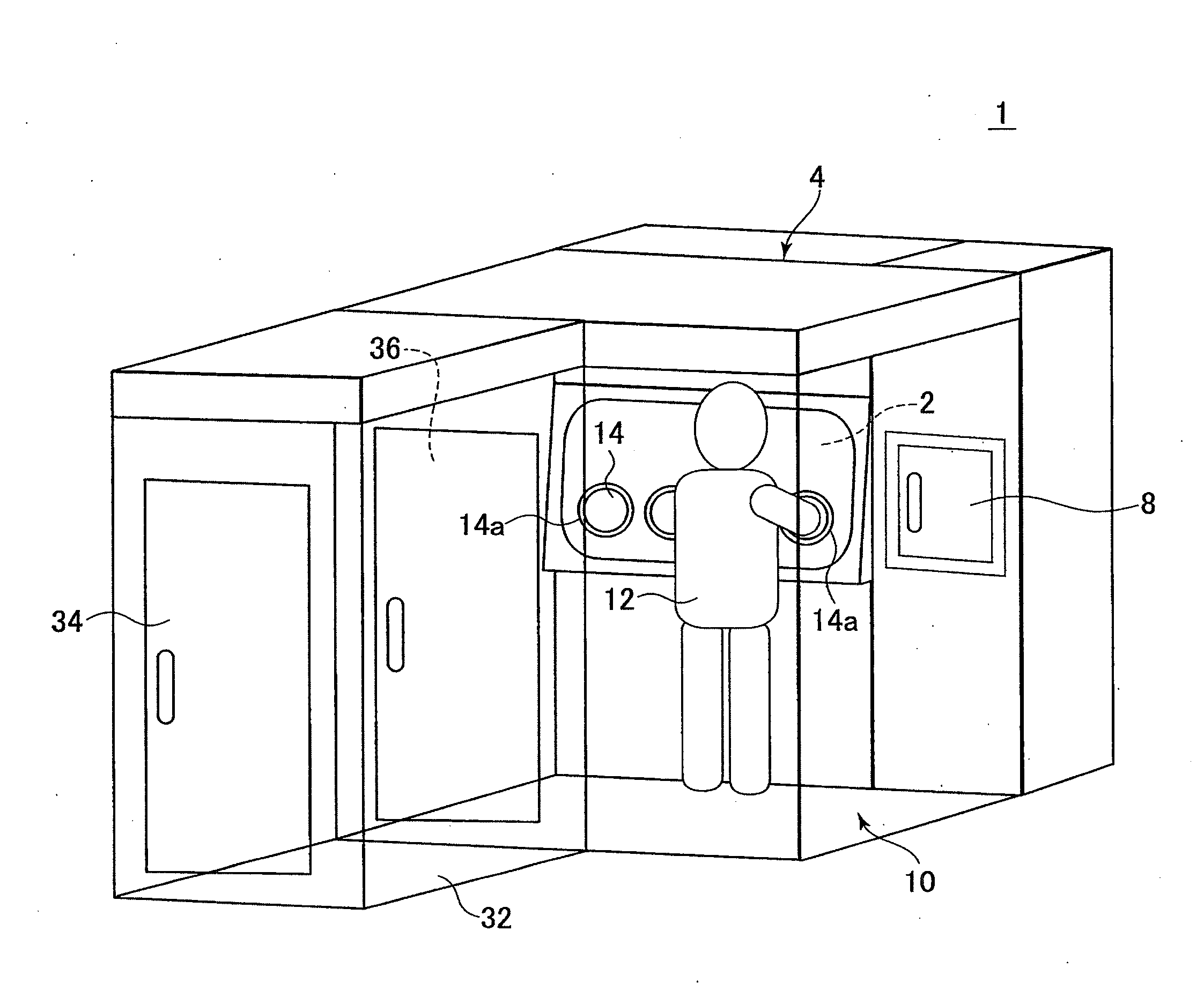
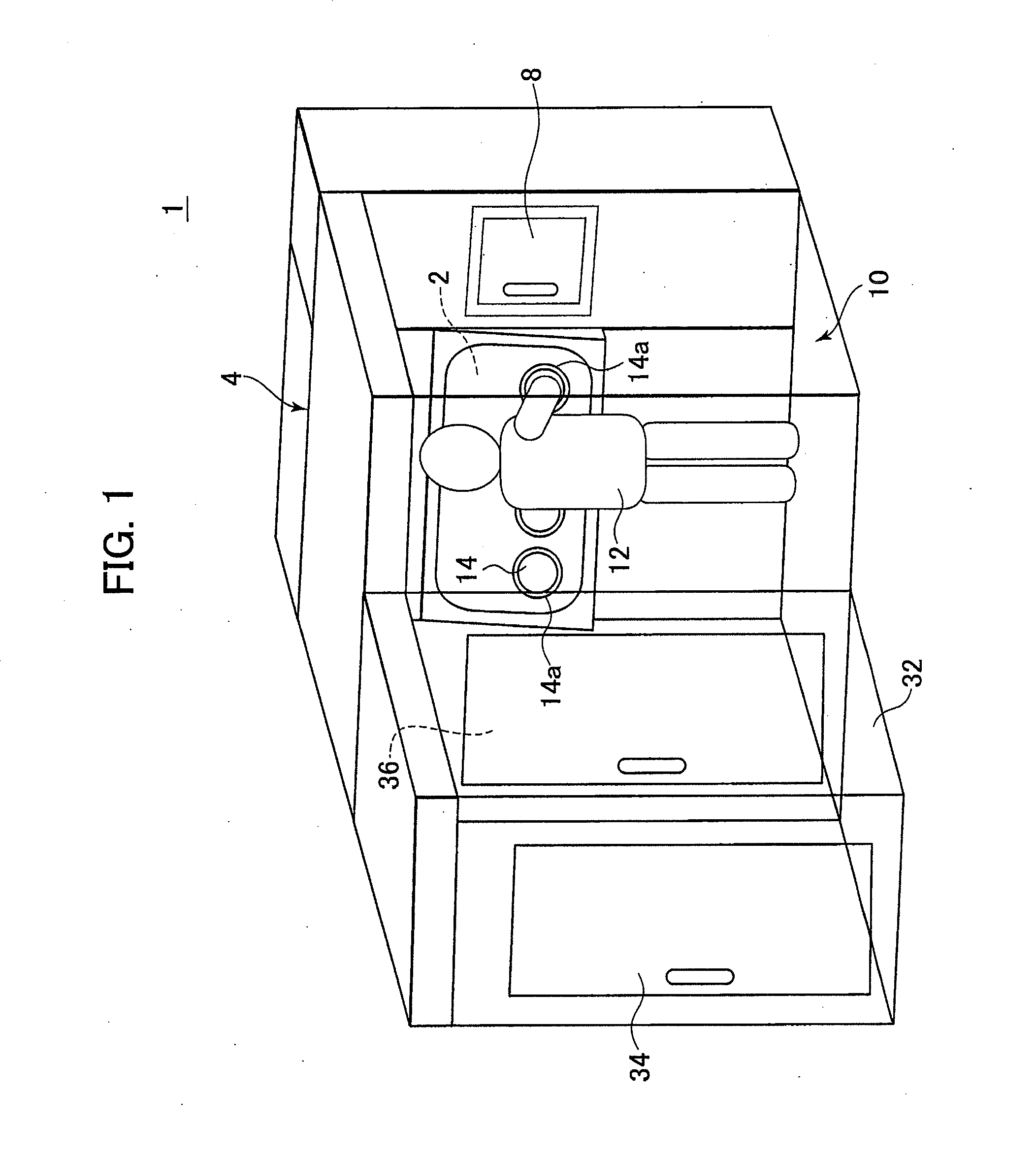
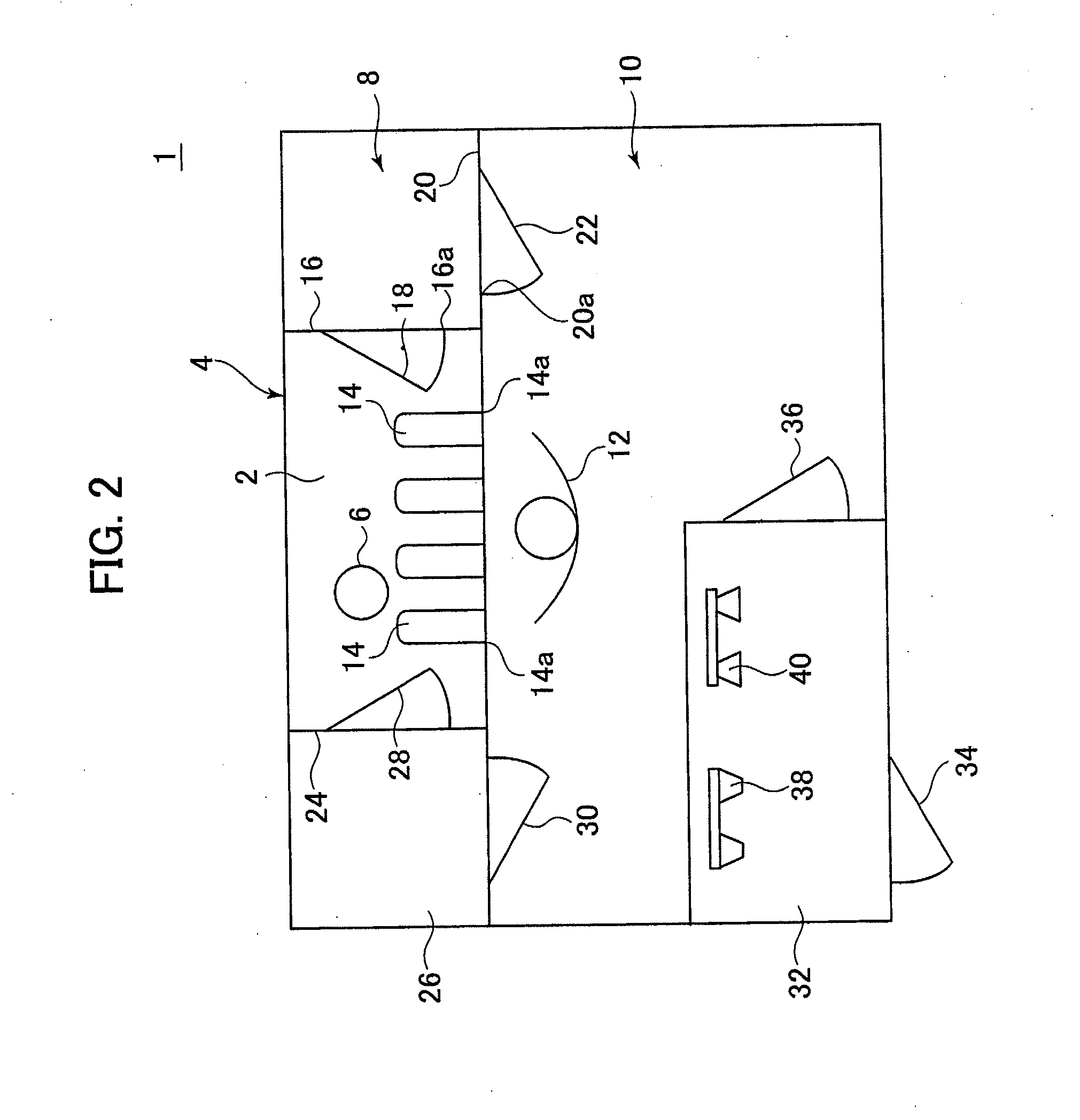
[0017]In the following, the present invention will be described with a first embodiment which is illustrated in the drawings. An isolator system 1 includes an isolator compartment (isolator) 4 with a sterile operation area 2 formed therein, and a pass box 8 through which an object 6 (in the present embodiment, a culture vessel for human cells and tissues, or the like) is inserted and removed from the operation area 2. The isolator system 1 allows an operator 12 to enter thereinto. Further, as described later, the isolator system 1 includes a clean booth 10 which encloses a section from which an operator can work with the object in the isolator compartment 4 and a section through which objects can be placed into the pass box 8.

[0018]The sterile operation area 2 capable of maintaining a grade A cleanliness environment A is formed inside the isolator compartment 4. A glove 14 is arranged as a wearing entity with which the operator 12 positioned outside of the isolator compartment 4 pro...

second embodiment

[0059]The isolator system 201 is not provided with a pass box with a decontamination capabilities for the object 206 brought into the sterile operation area 202, which is arranged in the isolator compartment 204. Here, in order to enhance cleanliness stepwise, each of the entrance pass box 222, the relay pass box 240, and the inlet pass box 208 is arranged as an intermediate air lock room and the dust removal pass box 228 and the sterile pass box 242 are arranged as grade C and grade B environment, respectively. In each pass box, when one door is opened, the other door is closed to prevent direct communication between environments of different grades. According to the above, the object 206 can sequentially pass through intermediate air lock rooms while performing open-close operation of the respective open-close doors 224, 236, 244, 254, 258, 218. As a result, research and processing can be carried out on cultures of human cells and tissues, and the like in a grade A cleanliness en...


PUM


Abstract

An isolator system includes an isolator, a pass box, a clean booth, and a determination gas supply unit. The isolator includes a sterile operation area formed therein and a wearing entity for an operator to operate externally. The pass box is arranged for introducing an object into the sterile operation area. The clean booth, in which an operator can enter, encloses at least an external insertion port of the wearing entity arranged in the isolator and an object inlet port for introducing the object into the pass box, and includes a clean gas supply unit to supply clean gas to an internal space thereof. The decontamination gas supply unit supplies decontamination gas into the sterile operation area and the clean booth. The isolator, the pass box, and the clean booth are arranged in a building. An interior air pressure of the clean booth is maintained equal to or higher than an ambient air pressure in the building, but lower than an interior air pressure of the sterile operation area after the interiors of the sterile operation area and the clean booth are decontaminated with the decontamination gas.

Description

BACKGROUND OF THE INVENTION[0001]1. Field of the Invention[0002]The present invention relates to an isolator system including an isolator, in which a sterile operation area is arranged, and a pass box for introducing an object into the sterile operation area.[0003]2. Description of the Related Art[0004]Currently, a culture of human cells and tissues, and the operation and research thereof are performed in a facility called a cell processing center (CPC). In such a facility, the interior of a building is divided into a plurality of rooms and these rooms are arranged so that cleanliness thereof is enhanced stepwise. A space in which a cell vessel is opened is an important operation region required to have the highest cleanliness environment of grade A. An ambient environment thereof, which is a direct support region, is required to be grade B with the second highest cleanliness. Further, a two-step improvement of cleanliness is required to go from a general environment of grade D thro...

Claims


Application Information

Patent Timeline
IPC IPC(8): B25J21/00F24F3/16
CPCF24F3/161B25J21/005B25J21/02C12M37/00F24F3/167A61G10/005
Inventor TANIMOTO, KAZUHITO
Owner SHIBUYA IND CO LTD
Why Eureka
Try Eureka