Shale fracture flow simulation apparatus

a flow simulation and fracture technology, applied in the direction of design optimisation/simulation, survey, borehole/well accessories, etc., can solve the problems of shale oil and gas tightly held, difficult to release, and vertical fracture to open, and slow the industry's learning curve in how to divert fluids

Inactive Publication Date: 2014-10-02
BAKER HUGHES INC
View PDF3 Cites 30 Cited by
  • Summary
  • Abstract
  • Description
  • Claims
  • Application Information

AI Technical Summary

Problems solved by technology

Specially engineered fracturing fluids are pumped at high pressures and rates into the reservoir interval to be treated, causing a vertical fracture to open.
Oil and gas in shale is tightly held and difficult to release.
It is possible lack of experimental laboratory data has slowed the industry's learning curve in how to divert fluids and distribute proppants in complex fracture networks.

Method used


Image

  • Shale fracture flow simulation apparatus
  • Shale fracture flow simulation apparatus
  • Shale fracture flow simulation apparatus

Examples


Embodiment Construction

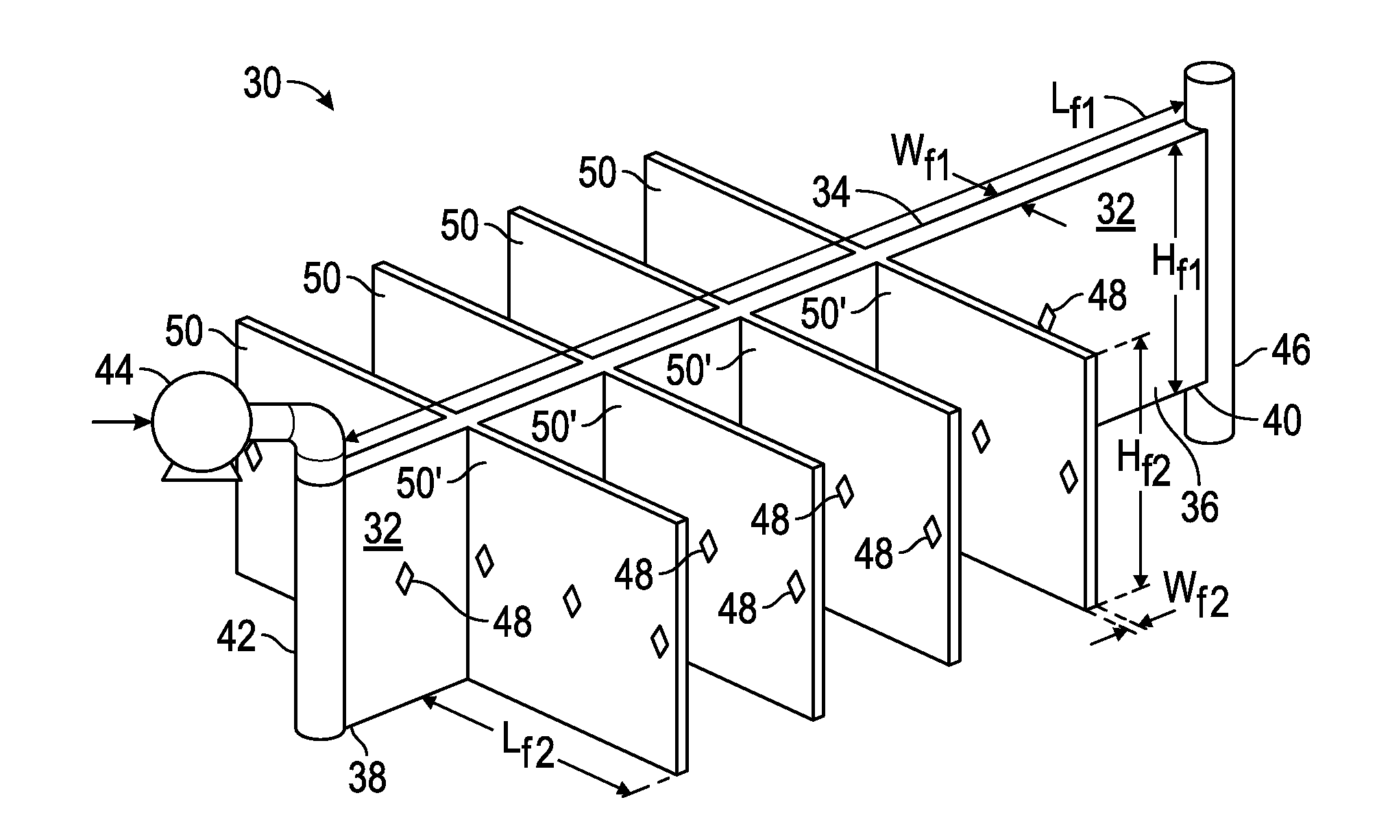
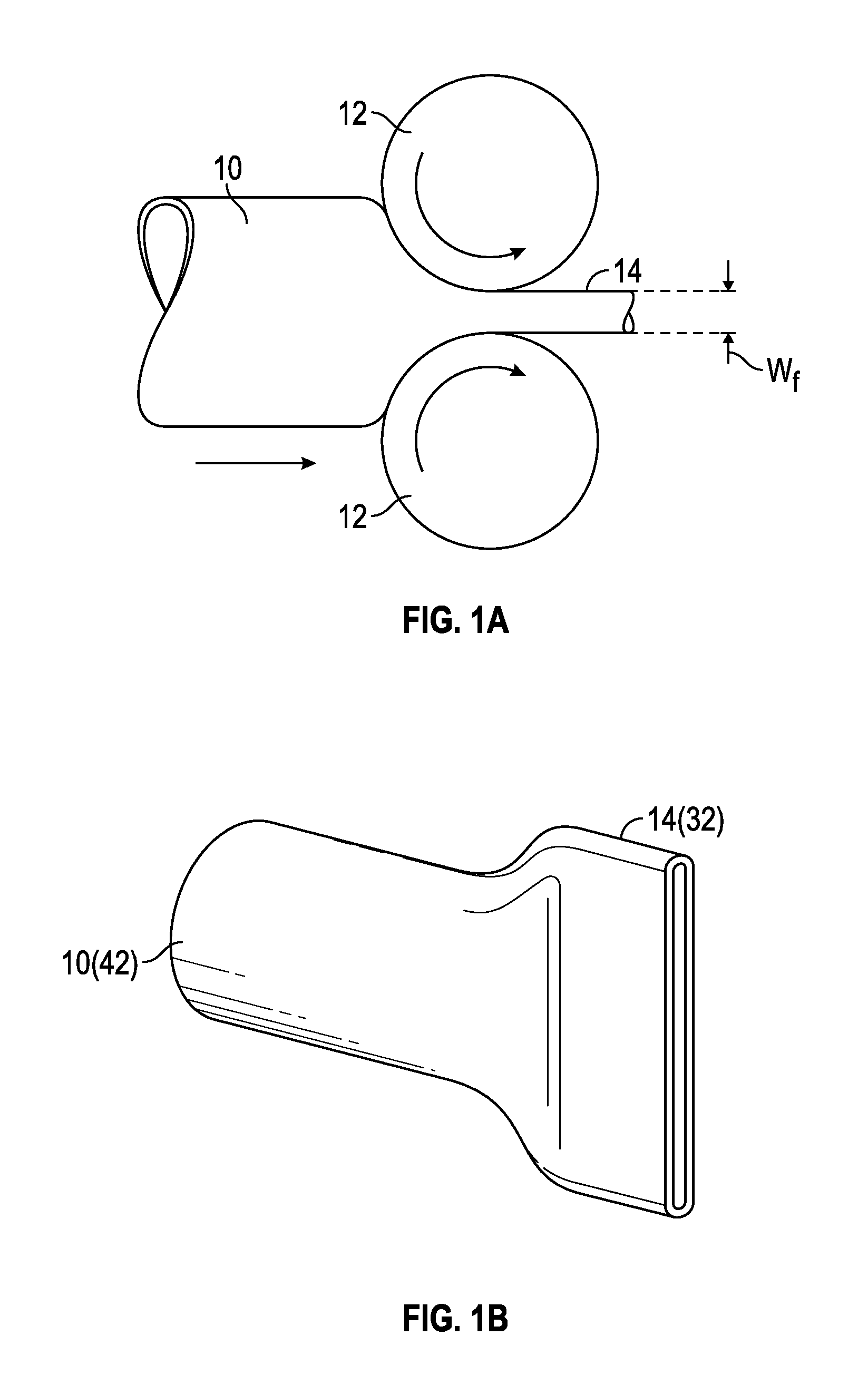
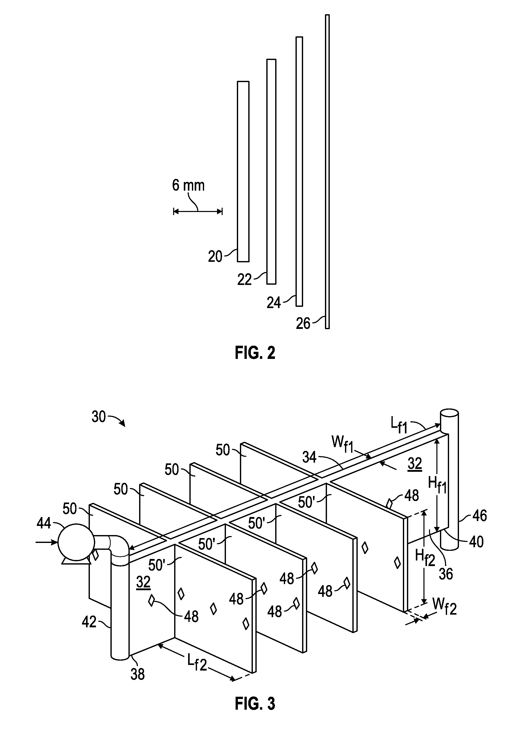
[0021]A method and apparatus have been discovered that may be used to experimentally evaluate the flow of treatment fluids within narrow shale-type fractures. The method is based on artificially creating varying width, height and length “fractures” by flattening tubing (or pipes), or otherwise constructing conduits with relative large height / width ratios, and connecting them to resemble fractures.

[0022]Several material and manufacturing methods may be employed to produce flatten tubing with different gauged internal widths, as described and shown in the Figures. Alternatively, fracture-like conduits may be constructed from multiple parts. A wide range of equipment may be configured to build a shale fracture flow apparatus contemplated herein including, but not necessarily limited to, flow system pumps, accumulators, connections, pressure transducers, pressure discs, gauged cross-intersections, fluid collection chambers, thermo-couples, automation hardware and software, and the like....


PUM


Abstract

An apparatus having conduits, flattened tubing or pipes of varying widths, heights and/or lengths may simulate a network of fractures that may be used to experimentally evaluate the flow of treatment fluids (e.g. fracturing fluids) within narrow, shale-type fractures. The tubing or pipes each have an interior space with a height and a width, and in one non-limiting embodiment the ratio of height/width is at least 10. The conduits may be constructed of flattened tubing or constructed from components designed and engineered to have the correct height/width ratio. The apparatus may be used to empirically develop diversion principles, more precise numeric models and the parameter relationships that control fluid diversion, secondary fracture initiation and the development of complex fracture networks.

Description

CROSS-REFERENCE TO RELATED APPLICATION[0001]This application claims the benefit of U.S. Provisional Patent Application Ser. No. 61 / 805,807 filed Mar. 27, 2013, incorporated herein by reference in its entirety.TECHNICAL FIELD[0002]The present invention relates in one non-limiting embodiment to methods and apparatus to model and obtain data on the flow of fluids and proppants in subterranean formations, and more particularly relates, in another non-restrictive version, to methods and apparatus to model and obtain data on the flow of fluids and proppants in subterranean formations that can be employed in a laboratory.TECHNICAL BACKGROUND[0003]Hydraulic fracturing of subterranean formations to extract hydrocarbons such as oil and gas is well known. Hydraulic fracturing (or “fracking”) involves a stimulation treatment performed on oil and gas wells in low-permeability reservoirs. Specially engineered fracturing fluids are pumped at high pressures and rates into the reservoir interval to ...

Claims


Application Information

Patent Timeline
Patent Type & Authority Applications(United States)
IPC IPC(8): E21B49/00
CPCE21B49/008E21B43/26E21B47/10G06F30/28
Inventor CREWS, JAMES B.HURT, ROBERT SAMUEL
Owner BAKER HUGHES INC
Why Eureka
Try Eureka