Self-radiating-type fracture nursing splint

A self-heating and splint technology, applied in the field of medical appliances, can solve the problems of low comfort for patients, poor heat dissipation, swelling of injured limbs, etc., so as to improve the comfort of use and help recovery.

Inactive Publication Date: 2017-11-17
杨露萍
View PDF3 Cites 9 Cited by
  • Summary
  • Abstract
  • Description
  • Claims
  • Application Information

AI Technical Summary

Problems solved by technology

Theoretically, the plaster bandage method is in good alignment with the shape of the extremity. However, after the surgical reduction of the orthopedic injury, the injured extremity is often swollen, and the swelling must be reduced before the plaster fixation is performed, which makes it impossible to fix the orthopedic injury immediately after the surgical reduction and misses the opportunity. It cannot be applied to the requirements of fracture sites of different thicknesses, and the air permeability is poor
The splint bandage method, because the splint is directly pressed on the skin, the blood vessels will not flow if it is too tight, and the fixation effect will not be achieved if it is too loose. When relaxing blood circulation and changing dressings at regular intervals, orthopedic surgeons with many years of clinical experience need to carefully bandage and fix the splint. It is cumbersome, and if the operation is not careful and the alignment is not fixed properly, it may cause bone injuries and limbs that cannot heal normally
[0003] For this reason, Chinese patent CN204951278U discloses a kind of inflatable orthopedic care splint, comprises strip air bag, first splint

Method used


Image

  • Self-radiating-type fracture nursing splint
  • Self-radiating-type fracture nursing splint

Examples


Embodiment Construction

[0013] The technical solution of this patent will be further described in detail below in conjunction with specific embodiments.

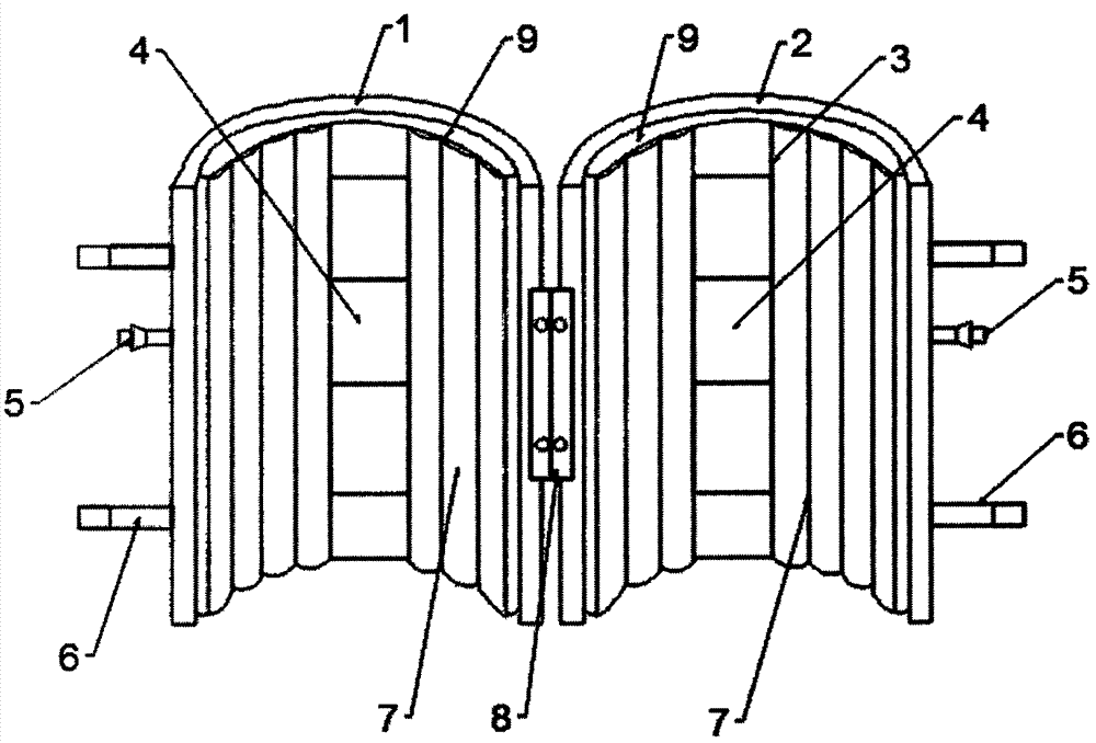
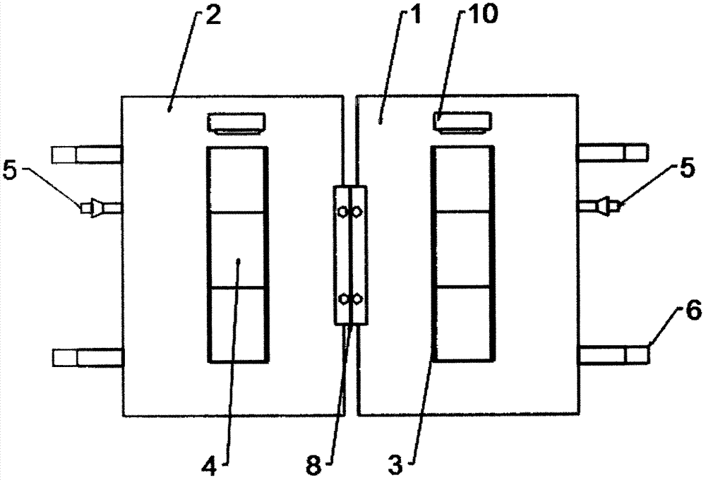
[0014] see Figure 1~2 , a self-radiating splint for fracture care, including a bar-shaped air bag 7, a first splint 1, and a second splint 2, the first splint 1 and the second splint 2 are connected and fixed by a hinge 8, and the left side of the first splint 1 and the right side of the second splint 2 are correspondingly provided with a plurality of straps 6, the sections of the first splint 1 and the second splint 2 are arc-shaped and arranged oppositely, and the inner sides of the first splint 1 and the second splint 2 are all provided with The arc-shaped large cushion body 9 has a hollow structure inside the large cushion body 9, and several strip airbags 7 are distributed at equal intervals on the upper surface of the large cushion body 9. The inside of the strip airbag 7 is connected with the large cushion body 9. Both the strip-shaped air...


PUM


Abstract

The invention discloses a self-radiating-type fracture nursing splint which comprises strip-shaped air bags, a first splint body and a second splint body. The first splint body and the second splint body are connected and fixed through a hinge, and the left side of the first splint body and the right side of the second splint body are provided with a plurality of binding belts correspondingly. The cross sections of the first splint body and the second splint body are each in an arc shape, and the inner sides of the first splint body and the second splint body are each provided with an arc-shaped large cushion body. The multiple strip-shaped air bags are distributed on the upper surfaces of the large cushion bodies at equal intervals, and the interiors of the strip-shaped air bags communicate with the large cushion bodies. A one-way air inlet valve is installed on each large cushion body, hollow-out grooves are formed in the middles of the first splint body and the second splint body, and long-strip-shaped installation frames matched with the splint bodies in shape are arranged in the hollow-out grooves. The installation frames are internally provided with a plurality of tightly-arranged semiconductor-refrigerating chips from top to bottom, and the multiple semiconductor-refrigerating chips arranged in the middles of the splint bodies achieve the cooling and radiating effects, so that when wearing the splint, a patient does not feel stuffiness, the use comfort of the patient is increased, and recovery of the patient is facilitated.

Description

technical field [0001] The invention relates to the field of medical appliances, in particular to a self-radiating splint for fracture care. Background technique [0002] In the nursing and treatment of orthopedic patients, especially after limb fracture surgery, in order to maintain the stability of bone alignment after surgery, avoid secondary injuries to the wounded, and ensure the normal healing and rehabilitation of orthopedic patients, it is necessary to reset the fractured limbs fixed. Generally, Western medicine adopts the plaster bandage method, that is, cotton gauze, raw gypsum and water are used to wrap the fracture site. After the gypsum solidifies, a hard shell is formed to keep the limbs in their normal positions. And general Chinese medicine is to adopt splint bandage method, presses the position of fracture with splint, fixes with bandage again. Theoretically, the plaster bandage method is in good alignment with the shape of the extremity. However, after th...

Claims


Application Information

Patent Timeline
IPC IPC(8): A61F5/058A61F7/00
CPCA61F5/058A61F7/00A61F7/007
Inventor 杨露萍
Owner 杨露萍
Why Eureka
Try Eureka