System for mounting solar modules

a solar module and solar panel technology, applied in the direction of heat collector mounting/support, machine supports, light and heating apparatus, etc., can solve the problems of difficult construction or otherwise assembling of photovoltaic arrays

Inactive Publication Date: 2014-10-02
KANZO PROD
View PDF16 Cites 3 Cited by
  • Summary
  • Abstract
  • Description
  • Claims
  • Application Information

AI Technical Summary

Benefits of technology

[0003]Solar module racks are used to mount solar modules onto different types of roofs and grounds areas to form a photovoltaic array. Constructing or otherwise assembling the photovoltaic arrays is challenging for many different reasons. The photovoltaic arrays are located in outside environments and thus must be designed to withstand the outside elements. The photovoltaic arrays must be designed to live long lives. Further, as in most any industry, reducing costs is important and therefore the costs of the parts as well as ease of assembling are important in assembling photovoltaic arrays.
[0005]Each rack may comprise a tray having a first tower supporting the upper mounting surface, a second tower supporting the lower mounting surface extending generally parallel to the first tower, and a base interconnecting the first tower and the second tower. The first and second towers extend generally perpendicular to the base and the upper mounting surface and lower mounting surface extend at an angle relative to the base. The base may include a plurality of ribs extending between the upper and lower mounting surface configured to elevate ballast placed on the base and provide rigidity to the tray. The tray may have a rounded peripheral edge.

Problems solved by technology

Constructing or otherwise assembling the photovoltaic arrays is challenging for many different reasons.

Method used


Image

  • System for mounting solar modules
  • System for mounting solar modules
  • System for mounting solar modules

Examples


Embodiment Construction

[0017]The present disclosure is directed to a solar module system and components of the solar module system. While the present disclosure may be embodied in many different forms, several specific embodiments are discussed herein with the understanding that the present disclosure is to be considered only as an exemplification of the principles of the disclosure, and it is not intended to limit the disclosure to the embodiments illustrated.

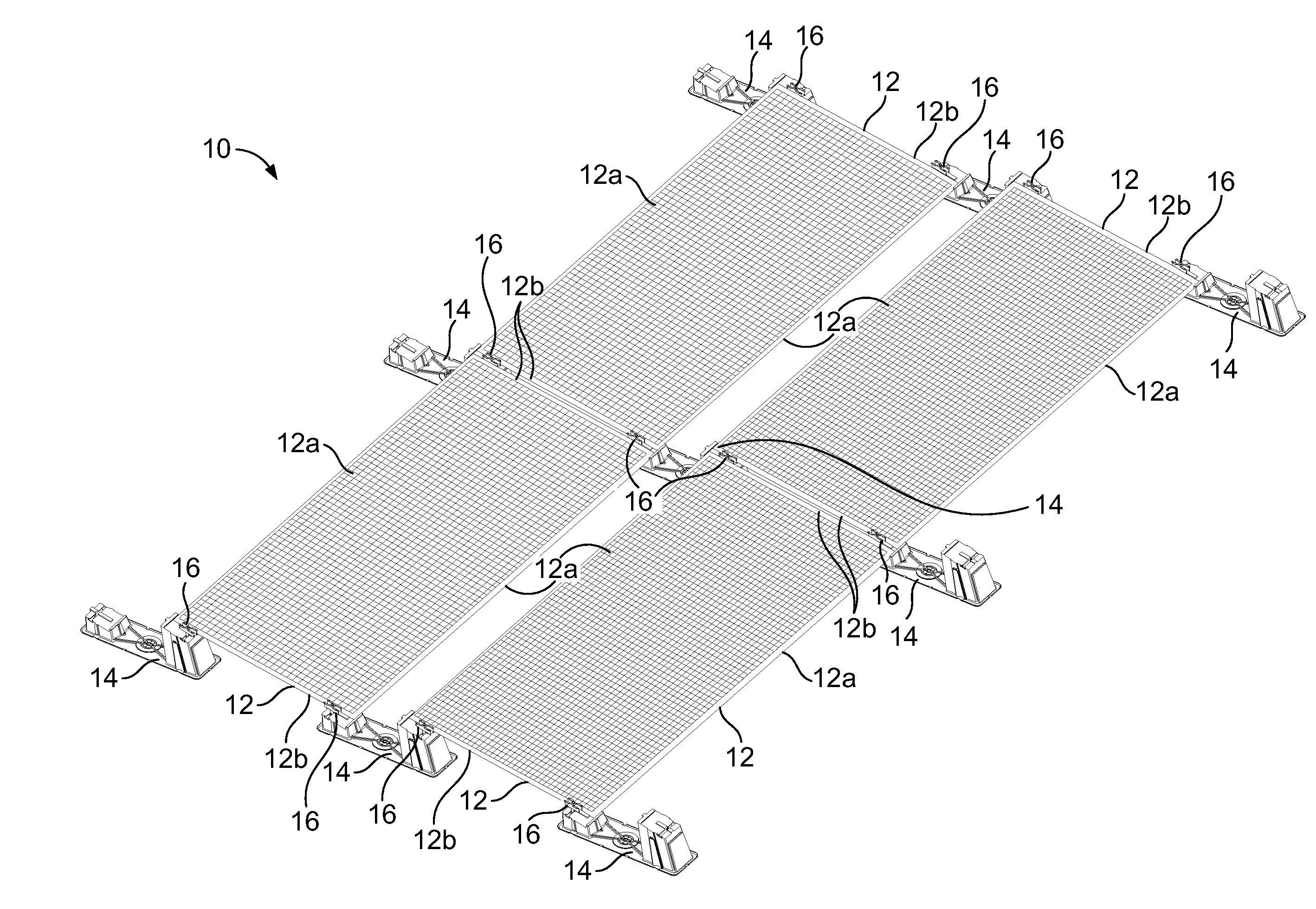
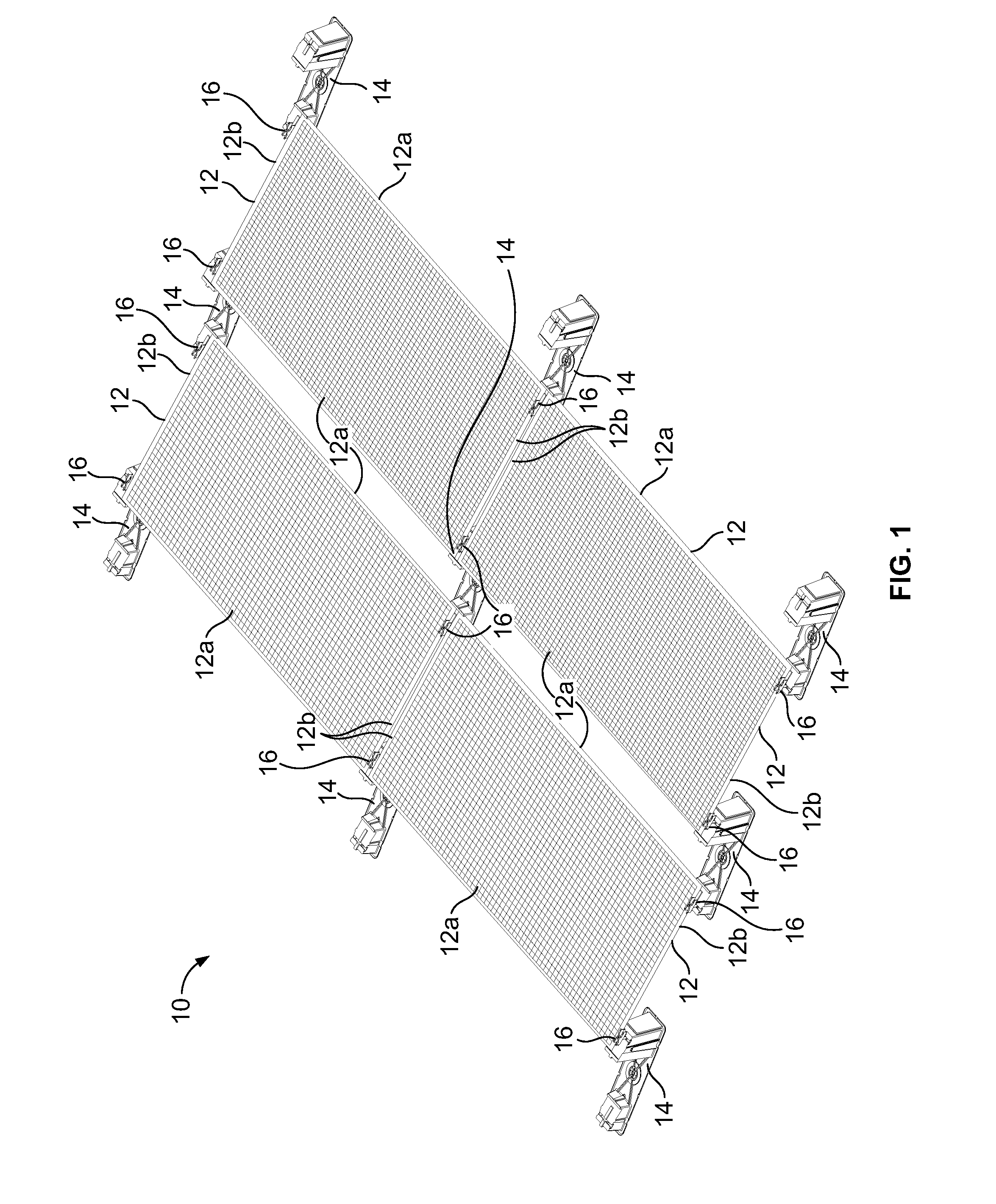
[0018]FIG. 1 illustrates a photovoltaic array 10 comprising two rows of solar modules 12 mounted to a low sloping roof or other roof or other surface by a solar racking system in accordance with an illustrated embodiment of the present disclosure. The illustrated solar racking system generally includes a plurality of racks 14 and a plurality of clamps 16 for securing the solar modules 12 to the racks. The photovoltaic array 10 may comprise any number of rows and columns of solar modules 12 or may have any other suitable configuration in accordance w...


PUM

PropertyMeasurementUnit
angleaaaaaaaaaa
widthaaaaaaaaaa
lengthaaaaaaaaaa

Abstract

A system for mounting solar modules comprising a plurality of racks and clamps. Each rack has an inclined upper mounting surface to support one of the solar modules and an inclined lower mounting surface to support one of the other solar modules. Each upper mounting surface and lower mounting surface define a slot. One of the clamps slidably receivable by a slot of one of the upper mounting surfaces and configured to secure the one solar modules to the upper mounting surfaces and an other of the clamps slidably receivable by a slot of one of the lower mounting surfaces and configured to secure said one of the other solar modules to one of the lower mounting surfaces. Each rack has a tray having a first tower supporting the upper mounting surface and a second tower supporting the lower mounting surface.

Description

CROSS REFERENCE TO RELATED APPLICATIONS[0001]This application is a Continuation of co-pending patent application Ser. No. 13 / 839,103, filed Mar. 15, 2013, which claims priority from U.S. Provisional Patent Application Ser. Nos. 61 / 660,394 filed Jun. 15, 2012, and 61 / 666,507 filed Jun. 29, 2012, the contents of which applications are herein incorporated by reference in their entireties.BACKGROUND AND SUMMARY[0002]The present disclosure relates generally to a system for mounting solar modules.[0003]Solar module racks are used to mount solar modules onto different types of roofs and grounds areas to form a photovoltaic array. Constructing or otherwise assembling the photovoltaic arrays is challenging for many different reasons. The photovoltaic arrays are located in outside environments and thus must be designed to withstand the outside elements. The photovoltaic arrays must be designed to live long lives. Further, as in most any industry, reducing costs is important and therefore the ...

Claims


Application Information

Patent Timeline
Patent Type & Authority Applications(United States)
IPC IPC(8): H01L31/042
CPCH01L31/0422Y02E10/50Y02B10/12F16M13/02H02S20/00F24J2/5239F24J2/5258Y02E10/47H01L31/0484F24J2/5237F24S25/11F24S25/16F24S25/636H02S20/24Y02B10/10Y02B10/20Y10T29/49947H01L31/042
Inventor KANCZUZEWSKI, NICHOLASKANCZUZEWSKI, THOMAS J.REINKS, PETERNAGY, DONALD J.TOWNSEND, JOHN E.
Owner KANZO PROD
Why Eureka
Try Eureka