Upright chuck assembly

a chuck and assembly technology, applied in the field of chuck assembly, can solve the problem of not being convenient for the user to operate the chuck, and achieve the effect of low cost and easy installation of the chuck dei

Active Publication Date: 2014-10-02
VERTEX MACHINERY WORKS
View PDF9 Cites 2 Cited by
  • Summary
  • Abstract
  • Description
  • Claims
  • Application Information

AI Technical Summary

Benefits of technology

[0010]The present invention has advantages, wherein the insertion of the horizontal gear set is inserted into one of the adjustable members, and the T-wrench is mounted to the connection portion connection portion on the top of the vertical gear set to control the operation of the chuck unit relative to the object. The chuck unit can be cooperated with existed base, rotary device and extension to easily install the chuck deice to the vertical machine center at very low cost.

Problems solved by technology

This is not convenient for the user to operate the T-wrench 93.

Method used


Image

  • Upright chuck assembly
  • Upright chuck assembly
  • Upright chuck assembly

Examples


Embodiment Construction

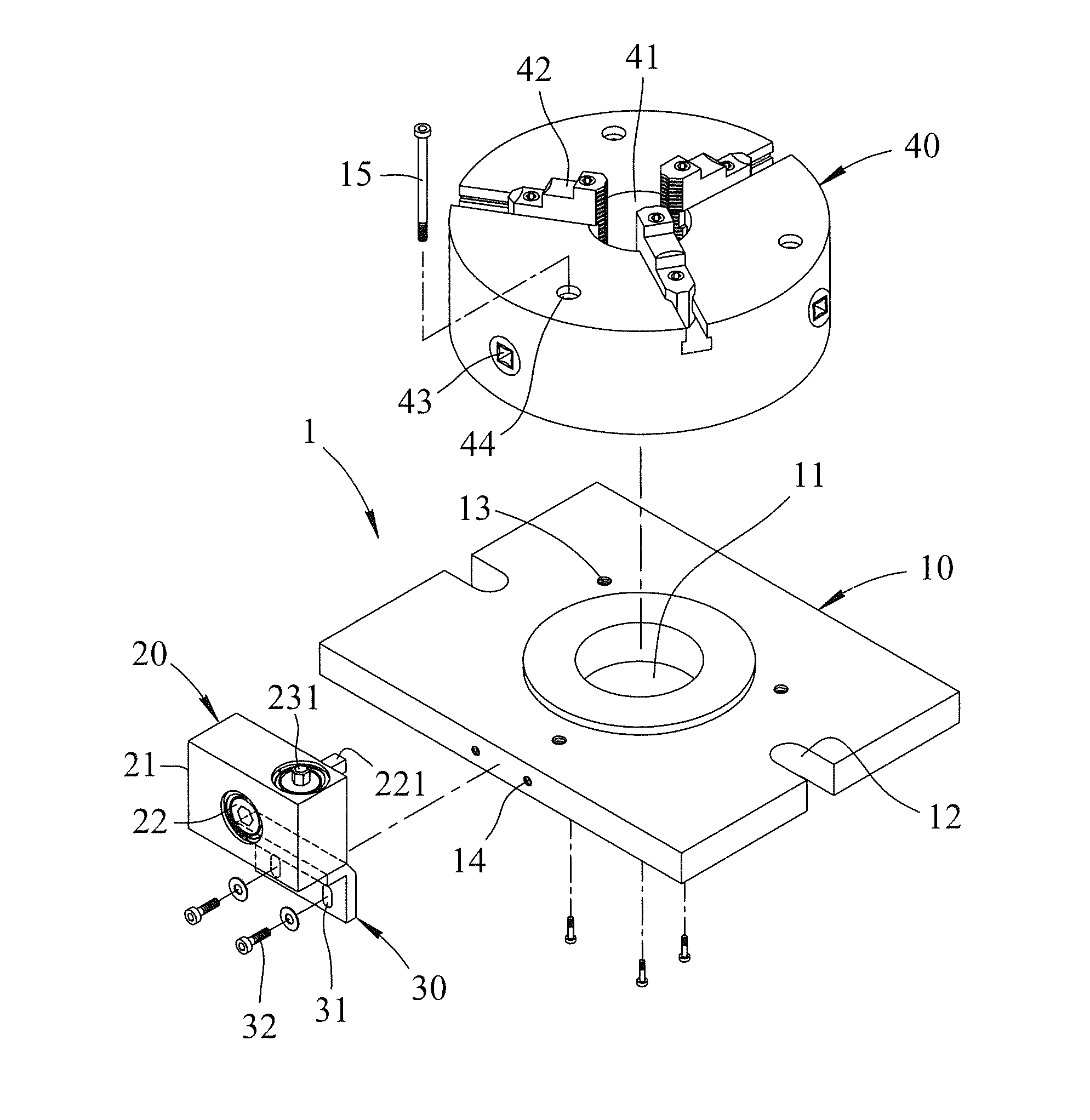
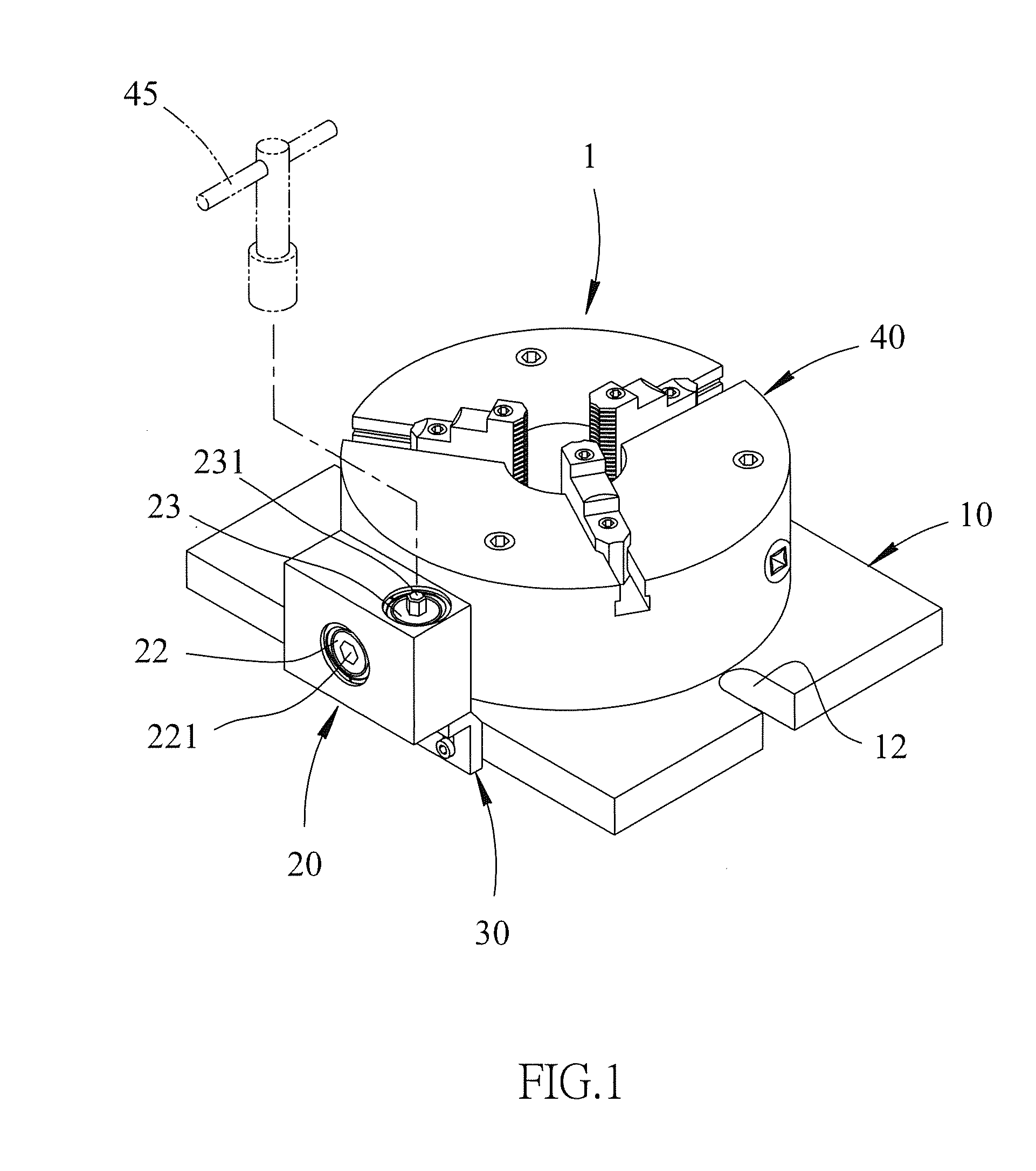
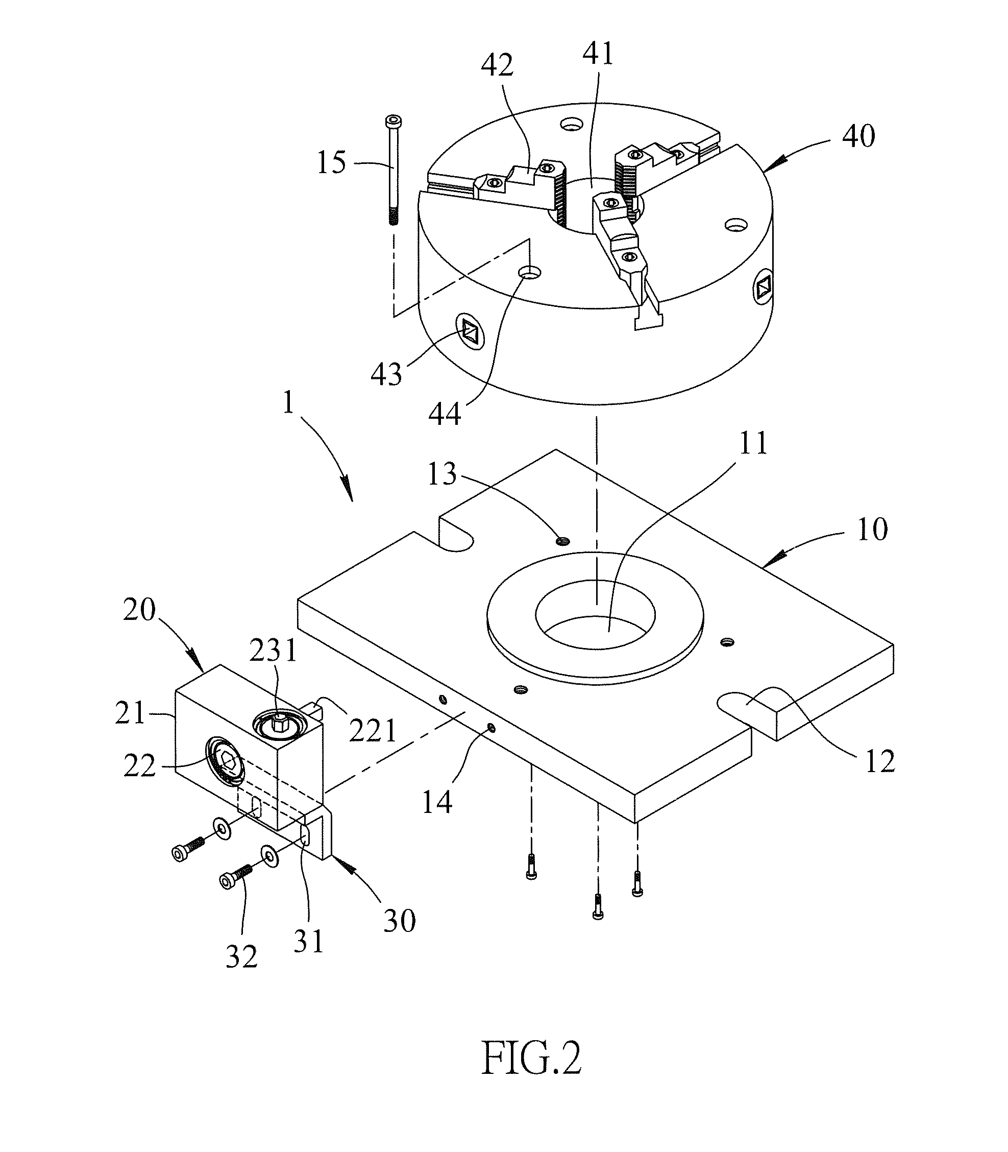
[0024]Referring to FIGS. 1 to 6, the chuck assembly 1 of the present invention comprises a base 10, a rotary device 20, an extension 30 and a chuck unit 40.

[0025]The base 10 has a central hole 11 so that debris during machining drop to the work bench 5 via the central hole 11. Two elongate notches 12 are respectively defined in two sides of the base 10 and two bolts extend through the notches 12 to fix the chuck assembly 10 to the work bench 5. Multiple first holes 13 are defined in the base 10 and located beside the central hole 11. Multiple second holes 14 are defined in one side of the base 10.

[0026]The rotary device 20 comprises a body 21, a horizontal gear set 22 and a vertical gear set 23. The horizontal gear set 22 and the vertical gear set 23 are engaged with each other in the body 21. An insertion 221 extends from the horizontal gear set 22 and is inserted into one of the adjustable members 43 to connect the horizontal gear set 22 to the base 10. The size of the insertion 2...


PUM


Abstract

An upright chuck assembly includes a base having two elongate notches respectively defined in two sides thereof. A rotary device is connected to the base and includes a horizontal gear set and a vertical gear set which are engaged with the horizontal gear set in the body of the rotary device. An insertion extends from the horizontal gear set and is inserted into one of the adjustable members. The vertical gear set has a connection portion on the top thereof, and a T-wrench is mounted to the connection portion. The rotary device is cooperated with a vertical machine center.

Description

BACKGROUND OF THE INVENTION[0001]1. Fields of the invention[0002]The present invention relates to a chuck assembly, and more particularly, to an upright chuck assembly.[0003]2. Descriptions of Related Art[0004]The conventional chuck assembly is used on a machine center which can be a horizontal machine center or a vertical machine center. Each of the two types of machine center has a chuck assembly. Vise is usually cooperated with a milling machine, drilling machine. Chuck is usually cooperated with a lathe.[0005]As shown in FIG. 11 which shows the China Patent No. CN202741779U and discloses a chuck assembly 9 which has a chuck unit 91 with three pawls 911 on a work bench 94, and multiple blocks 92 fix the chuck unit 91 on the work bench 94. The three pawls 911 automatically position a cylindrical object at the center of the chuck assembly so as to be machined conveniently.[0006]When the three pawls 911 are released from the object, a T-wrench 93 has to be inserted into an adjustmen...

Claims


Application Information

Patent Timeline
Patent Type & Authority Applications(United States)
IPC IPC(8): B23B31/16
CPCB23B31/16083B23B2260/07B23B2231/00B23B31/16004B23B31/24Y10T279/17Y10T279/1933
Inventor HUANG, HAN-NUNG
Owner VERTEX MACHINERY WORKS
Why Eureka
Try Eureka