
Eureka
For R&D, Eureka makes reading and utilizing patents & technical documents easy.
Eureka AIR
Designed for self-driven R&D workflows. Generate viable solutions, solve complex R&D challenges, empower your innovation with AI.

Eureka Materials
Designed for material experts only. Revolutionize your material R&D, from search, analyze, to developing new materials.

TechResearch
Generate reliable direction feasibility study reports for your R&D in just a few steps.

TechSeek
Discover and master advanced knowledge NOW. Basics, ideas, possibilities, all at once.

TechMind
As an expert in R&D Theories, TechMind can generates customized viable solutions instantly.

TechRisk
Analyze your overall solution with one click, know your potential R&D risks in advance.

TechMonitor
Get weekly tech updates, stay abreast of the latest tech innovations and key insights.
Illumination device and automotive lamp
- Summary
- Abstract
- Description
- Claims
- Application Information
AI Technical Summary
Benefits of technology
Problems solved by technology
Method used
Image

Examples
first embodiment
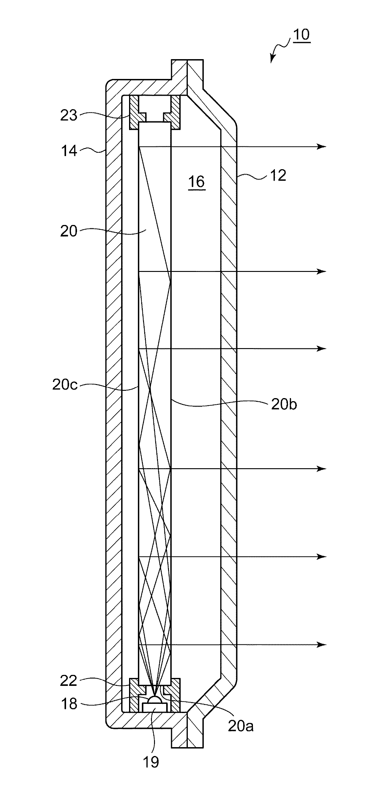
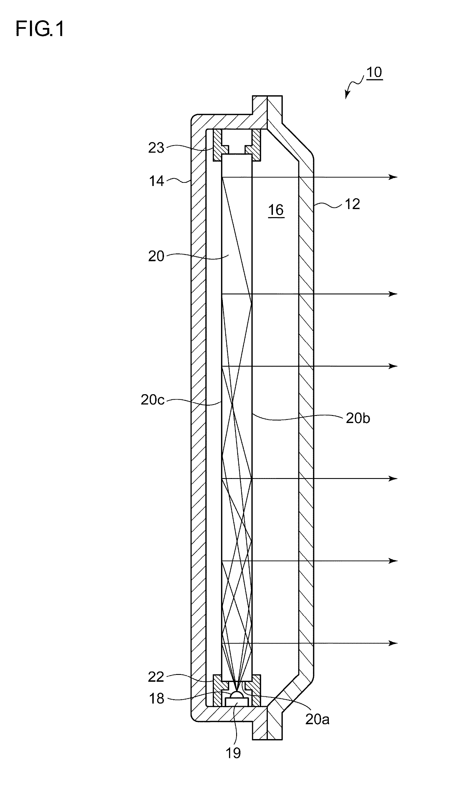
[0031]FIG. 1 is a cross-sectional view of an automotive lamp 10 according to a first embodiment of the present invention. The automotive lamp 10 according to the first embodiment may be used as a tail lamp or a stop lamp provided at a rear part of the vehicle.
[0032]The automotive lamp 10 includes a lamp body 14 and a transparent cover 12, which covers an opening in front of the lamp body 14. The lamp body 14 and the cover 12 form a lamp chamber 16. And an LED 18 and a light guide 20 are provided inside the lamp chamber 16.
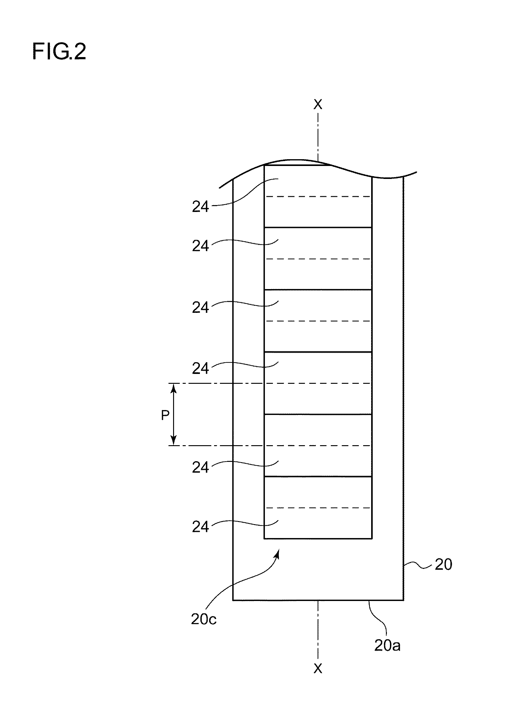
[0033]The light guide 20 is a rod-like member produced through the injection molding of a transparent resin such as acrylic or polycarbonate. Although, in FIG. 1, the light guide 20 is of a linear shape, the shape of the light guide 20 is not limited to any particular one and may be a curve shape, for example. Although in the present embodiment the cross-sectional shape of the light guide 20 perpendicular to an extending direction (longer direction) thereof is an a...
second embodiment
[0046]FIG. 6 is a cross-sectional view of an automotive lamp 60 according to a second embodiment of the present invention. The automotive lamp 60 according to the second embodiment may also be used as a tail lamp or a stop lamp provided at a rear part of the vehicle.
[0047]The automotive lamp 60 includes a lamp body 64 and a transparent outer lens 62, which covers an opening in front of the lamp body 64. The outer lens 62 is so formed as to be curved from a front area of the lamp toward the right and left sides. The lamp body 64 and the outer lens 62 form a lamp chamber 66. And provided inside the lamp chamber 66 are a bulb 68 functioning as a light source, a bulb socket 67 serving as a light source mounting part, a reflector 69 reflecting the light emitted from the bulb 68, and an inner lens 70 that controls the direct light from the bulb 68 and the light reflected from the reflector 69 and then emits them toward the outer lens 62.
[0048]The bulb 68 is supported by the bulb socket 67...
third embodiment
[0059]FIGS. 11A and 11B are diagrams for explaining an automotive lamp 100 according to a third embodiment of the present invention. The automotive lamp 100 according to the third embodiment is used as an interior lamp for use in a vehicle. FIG. 11A is a front view showing an appearance of the automotive lamp 100. FIG. 11B is a front view showing an internal structure of the automotive lamp 100.
[0060]The automotive lamp 100 includes a lamp body 104 and a lens 102, which covers an opening in front of the lamp body 104. FIG. 11B illustrates the automotive lamp 100 with the lens 102 removed from the lamp body 104. The lamp body 104 and the lens 102 form a lamp chamber 106. And provided inside the lamp chamber 106 are a light bulb 108 functioning as a light source, a light bulb mounting part 107, a switch knob 109, an electric circuit 110 used to switch on / off of the light bulb 108 in response to an operation of the switch knob 109, and so forth. The switch knob 109 is exposed outside t...
PUM
 Abstract
Description
Claims
Application Information
 - R&D Engineer
- R&D Manager
- IP Professional
- Industry Leading Data Capabilities
- Powerful AI technology
- Patent DNA Extraction
Browse by: Latest US Patents, China's latest patents, Technical Efficacy Thesaurus, Application Domain, Technology Topic, Popular Technical Reports.
© 2024 PatSnap. All rights reserved.Legal|Privacy policy|Modern Slavery Act Transparency Statement|Sitemap|About US| Contact US: help@patsnap.com