Laser

a laser and laser technology, applied in lasers, laser details, active medium materials, etc., can solve the problems of low stability, low power density loss, and low focus depth during long distance transmission

Active Publication Date: 2014-10-02
TSINGHUA UNIV +1
View PDF2 Cites 11 Cited by
  • Summary
  • Abstract
  • Description
  • Claims
  • Application Information

AI Technical Summary

Problems solved by technology

Most of the high power lasers are multi-mode lasers, and the laser beams have large divergence ang...

Method used


Image

  • Laser
  • Laser
  • Laser

Examples


Embodiment Construction

[0017]The disclosure is illustrated by way of example and not by way of limitation in the figures of the accompanying drawings in which like references indicate similar elements. It should be noted that references to “another,”“an,” or “one” embodiment in this disclosure are not necessarily to the same embodiment, and such references mean at least one.

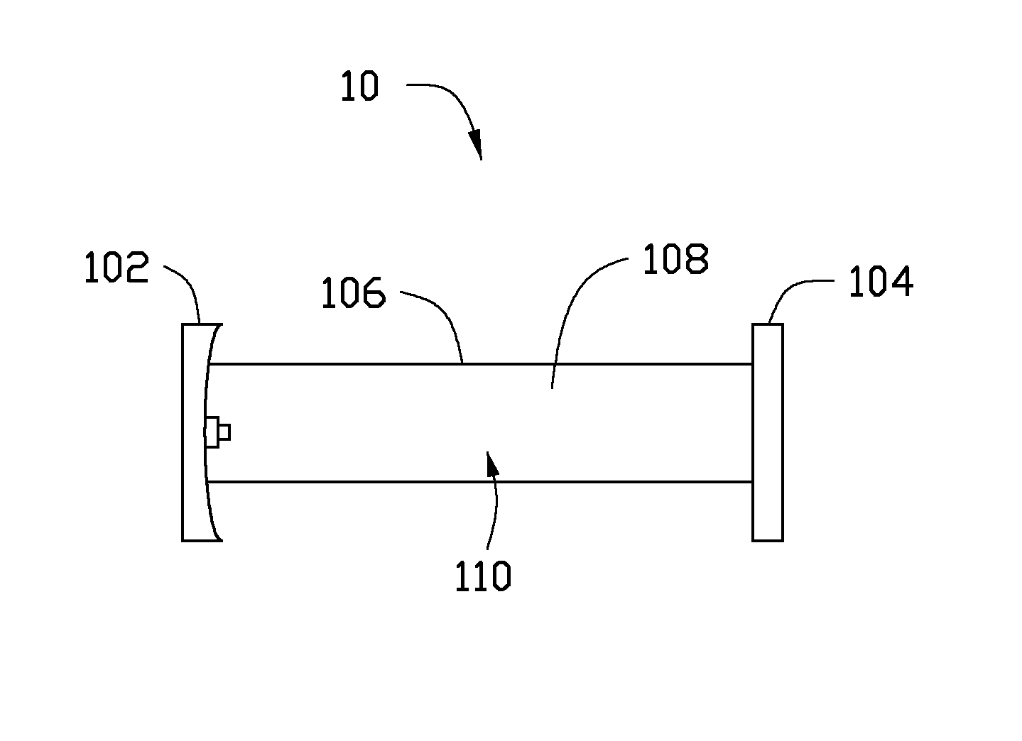
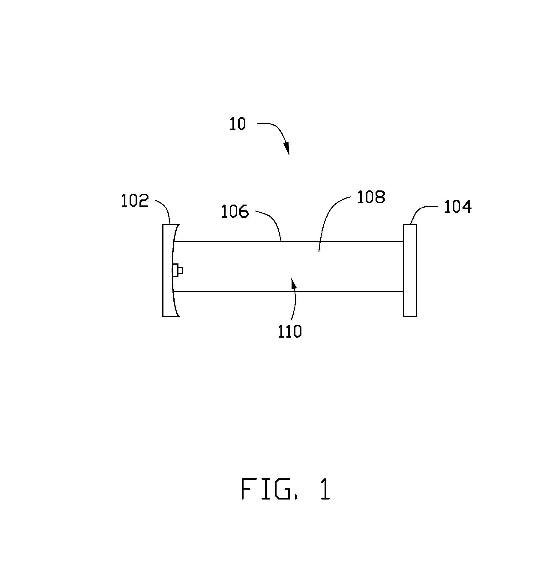
[0018]FIG. 1 is an embodiment of a laser 10. The laser 10 includes a total reflective mirror 102, an output mirror 104, a discharge lamp 106, and an active laser medium 108. The total reflective mirror 102 and the output mirror 104 are separately configured on two opposite ends of the discharge lamp 106. The total reflective mirror 102, the output mirror 104, and the discharge lamp 106 define a resonant cavity 110. The active laser medium 108 is filled in the resonant cavity 110.

[0019]Similar to some prior art, the laser 10 further includes two electrodes, a water-cooled jacket, a water inlet, a water outlet, a gas reservoir, a gas tub...


PUM


Abstract

A laser includes a total reflective mirror, an output mirror, a discharge lamp, and an active laser medium. The total reflective mirror, the output mirror, and the discharge lamp define a resonant cavity. The active laser medium is filled in the resonant cavity. The total reflective mirror includes a body, a metal film, and at least one microstructure. Each of the at least one microstructure is a step structure. The step structure includes a plurality of cylinders stacked with each other with respect to their diameters. Both the height and the diameter of the cylinders are in a range from about 0.5λ to about 2λ, while λ is a working wavelength of the laser.

Description

CROSS-REFERENCE TO RELATED APPLICATIONS[0001]This application claims all benefits accruing under 35 U.S.C. §119 from China Patent Application No. 201210573848.4, filed on Dec. 26, 2012 in the China Intellectual Property Office. This application is also related to application entitled, “LASER”, filed ______ (Atty. Docket No. US47186), “LASER”, filed ______ (Atty. Docket No. US47185), “LASER”, filed **** (Atty. Docket No. US47184), and “LASER”, filed ______ (Atty. Docket No. US47187). Disclosures of the above-identified applications are incorporated herein by reference.BACKGROUND[0002]1. Technical Field[0003]The present disclosure relates to lasers.[0004]2. Description of Related Art[0005]Because of the high power levels available, a variety of lasers are frequently used in industrial applications such as cutting and welding, and in military applications such as laser weapons.[0006]Most of the high power lasers are multi-mode lasers, and the laser beams have large divergence angle, sh...

Claims


Application Information

Patent Timeline
IPC IPC(8): H01S3/08H01S3/03
CPCH01S3/03H01S3/08068H01S3/2232H01S3/2222H01S3/0804H01S2301/20H01S3/08059H01S3/092H01S3/0407H01S3/041
Inventor ZHU, JING-LEIZHU, JUNLI, QUN-QINGJIANG, KAI-LIFENG, CHENJIN, GUO-FANFAN, SHOU-SHAN
Owner TSINGHUA UNIV
Why Eureka
Try Eureka