
Communication system with proactive network maintenance and methods for use therewith

a communication system and network maintenance technology, applied in the field of communication systems, can solve problems such as capacity shortages in cable plants operating at a frequency of 750 mhz, and channel capacity shortages

Active Publication Date: 2014-10-02
AVAGO TECH INT SALES PTE LTD
View PDF3 Cites 60 Cited by
  • Summary
  • Abstract
  • Description
  • Claims
  • Application Information

AI Technical Summary

Benefits of technology

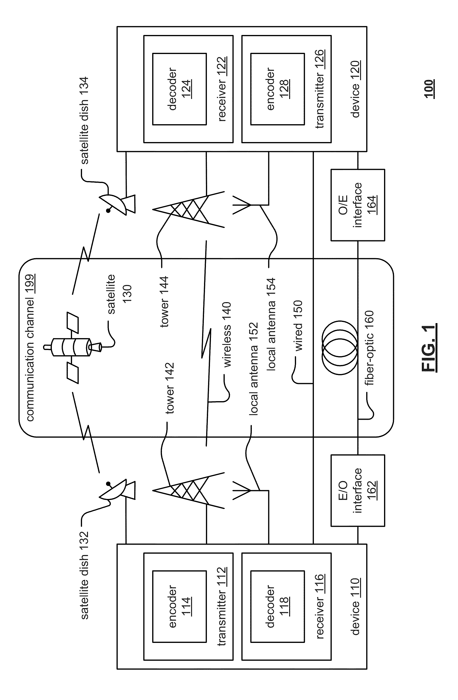
The patent text describes a communication system, specifically a point-to-multipoint communication system such as a cable modem system. The text discusses various methods to address issues related to bandwidth shortages and proposes solutions to improve downstream transmissions. The text also describes different embodiments of communication systems using OFDM and probe symbol insertion. The technical effects of the patent text include improved downstream bandwidth utilization, reduced channel capacity shortages, and improved transmission methods for data over cable systems.

Problems solved by technology

Advances in communication technology are requiring increasingly more bandwidth, which can lead to deficiencies in channel capacity, especially with respect to these downstream transmissions.
For example, even cable plants operating at a frequency of 750 MHz are being challenged with capacity shortages, due to increased demand for video on demand (VOD), high-definition television (HDTV), digital services, and expanding analog channel lineups.

Method used


Image

  • Communication system with proactive network maintenance and methods for use therewith
  • Communication system with proactive network maintenance and methods for use therewith
  • Communication system with proactive network maintenance and methods for use therewith

Examples


example 1

Pilot Estimation

[0054]The technique operation by subtracting the values of scattered pilots using a smoothed channel estimate. The result is an estimate of the noise floor at the pilot frequency, which moves across the whole band. The noise floor includes random noise and spurs. This can give performance 5-10 dB better than the required QAM SNR, e.g., over 40 dB. While this method is available in other receiver designs, as an enhancement, it can be used even in a broken channel, when only the PLC (Physical layer link channel) can be received by the CM 320. The CM 320 can have to report the measurements via the upstream through the broken plant condition as well. This can allow troubleshooting of broken plants.

[0055]In this example, the noise estimation works as follows. The received symbol on a scattered pilot bin is Y=H*X+N, where H is the channel response on scattered pilot (SP), X is the transmitted SP symbol, N is the noise, all in frequency domain. If the receiver channel estim...

example 2

Silent Pilot Probe

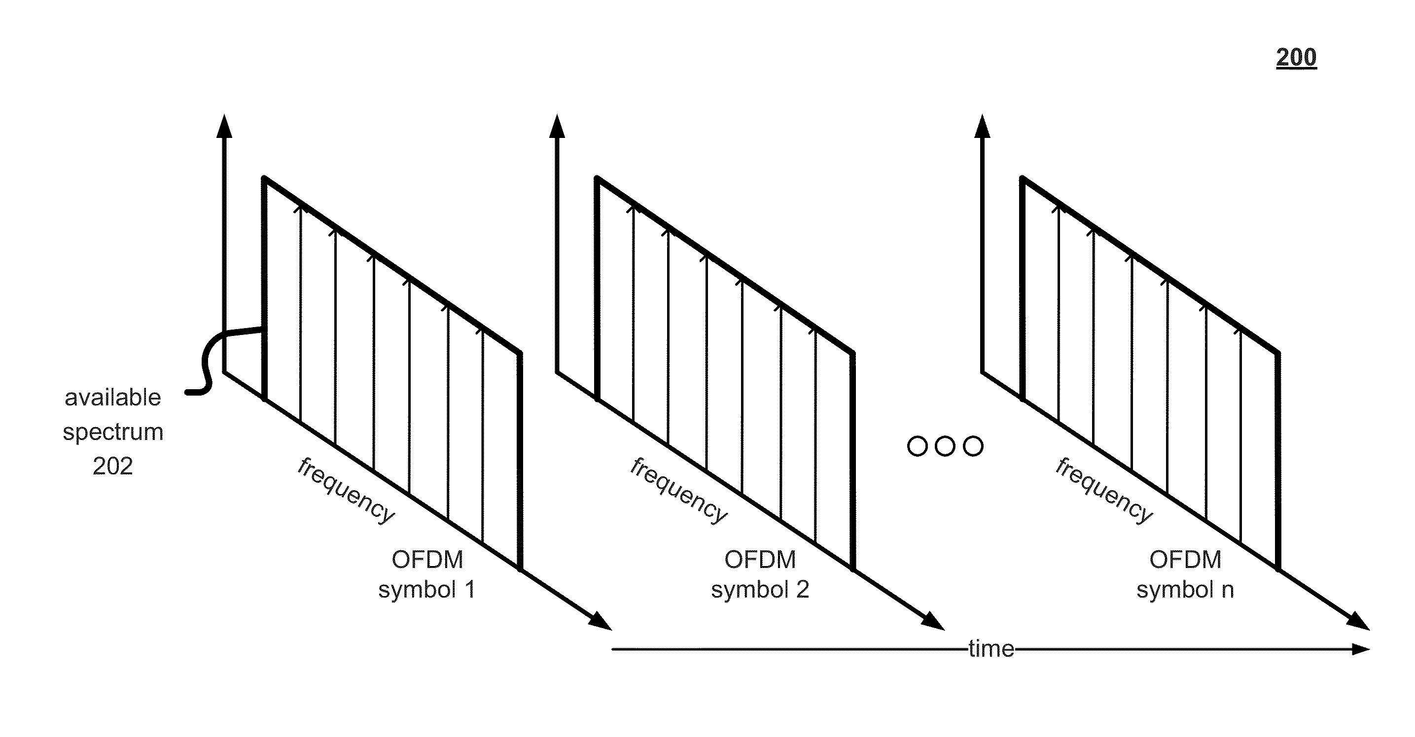
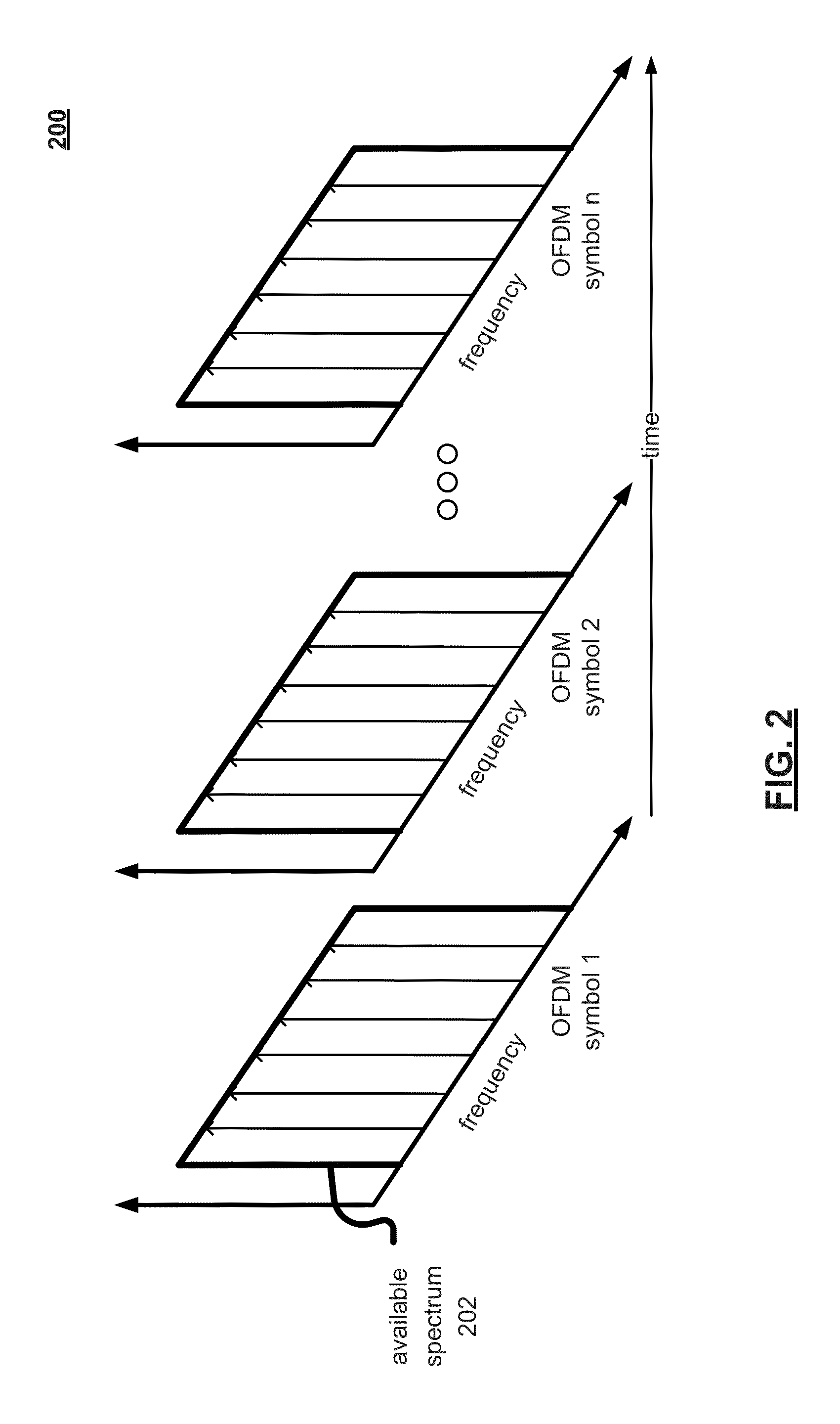
[0056]At the narrowband extreme, sweep a single tone or a few tones, with zero modulation, across the band. This is like having additional scattered pilots with zero (silent or null) modulation. This approach can cause minimal disruption to an existing system design. This can provide better performance than using the existing pilots in Example 1 since the channel estimate is not needed to subtract the pilot values, since the pilot values are zero. Considering a DOCSIS 3.1 implementation, the time and frequency interleaver 410 can place nulled input sub-carriers on randomized subcarrier locations across a number of frequencies and across a number of OFDM symbols equal to the interleaver depth. So, rather than sweeping, the interleaver 410 provides nulled subcarrier measurements at a randomized (but complete) set of subcarriers across multiple transmitted symbols.

example 3

Wideband (WB) Silent Probe

[0057]At the wideband extreme, pause downstream OFDM symbol stream every 1 second to 10 minutes and insert a quiet symbol across the entire 192 MHz band. This can be the most sensitive measurement but can require modifications in the PHY and MAC design. An example of this approach is presented in conjunction with FIG. 5.


PUM


Abstract

A transmitter for use in a cable modem termination system includes a data processing module that generates a plurality of OFDM symbols from a data packet. A probe symbol generator generates a probe symbol, as one of a plurality of probe symbol types. The probe symbol is selectively inserted within the plurality of OFDM symbols, at a pre-defined probe symbol interval.

Description

CROSS REFERENCE TO RELATED PATENTS / PATENT APPLICATIONS[0001]The present U.S. Utility patent application claims priority pursuant to 35 U.S.C. §119(e) to U.S. Provisional Application No. 61 / 806,274, entitled “COMMUNICATION SYSTEM WITH PROBE SYMBOL TRANSMISSIONS”, filed Mar. 28, 2013; U.S. Provisional Application No. 61 / 810,064, entitled “COMMUNICATION SYSTEM WITH PROBE SYMBOL TRANSMISSIONS FOR LEAKAGE LOCATION”, filed Apr. 9, 2013; U.S. Provisional Application No. 61 / 823,747, entitled “COMMUNICATION SYSTEM WITH PROBE SYMBOL TRANSMISSIONS OF DIFFERING TYPES”, filed May 15, 2013; U.S. Provisional Application No. 61 / 859,370, entitled “COMMUNICATION SYSTEM WITH CARRIER WAVE SYMBOL TRANSMISSIONS FOR LEAKAGE DETECTION”, filed Jul. 29, 2013; U.S. Provisional Application No. 61 / 862,907, entitled “COMMUNICATION SYSTEM WITH CARRIER WAVE TRANSMISSIONS FOR EGRESS MONITORING, PHASE NOISE TESTING AND / OR MEASUREMENT OF SUB-CARRIER SPACING”, filed Aug. 6, 2013; U.S. Provisional Application No. 61 / 89...

Claims


Application Information

Patent Timeline
Patent Type & Authority Applications(United States)
IPC IPC(8): H04B3/46H04L5/00H04L27/26
CPCH04B3/46H04L5/0048H04L27/2605H04L27/2613H04L25/0226H04L5/0007H04L27/26134H04L12/2885
Inventor CURRIVAN, BRUCE JOSEPHPRODAN, RICHARD STEPHENKOLZE, THOMAS JOSEPHZOU, HANLIGOMEZ, RAMON ALEJANDROMONTREUIL, LEOLAUBACH, MARK EDWARDFISH, ROGER WAYNEDENNEY, LISA VOIGTPANTELIAS, NIKI ROBERTAMIN, JONATHAN SOOKI
Owner AVAGO TECH INT SALES PTE LTD
Learn More