Composite structure

a composite material and composite material technology, applied in the field of composite materials, can solve the problems of inferior interface properties, and affecting the mechanical properties of the laminate material comprising thermoplastic and thermoset resin to some extent, so as to improve the mechanical properties of such a composite material

Active Publication Date: 2014-10-02
SIEMENS GAMESA RENEWABLE ENERGY AS
View PDF1 Cites 46 Cited by
  • Summary
  • Abstract
  • Description
  • Claims
  • Application Information

AI Technical Summary

Benefits of technology

The objective of this invention is to fix problems with traditional methods that combine thermoset resin and thermoplastic elements in composites. Specifically, it seeks to enhance the strength of these materials.

Problems solved by technology

The technical problem addressed in this patent text is the negative impact on the mechanical properties of wind turbine blades made from thermoset and thermoplastic resin composites. This is caused by the inferior material properties of the thermoplastic and the interface properties between the thermoplastic and thermoset resin layers. The amount of thermoplastic material in the composite structures is reduced as much as possible to address this problem.

Method used


Image

  • Composite structure
  • Composite structure
  • Composite structure

Examples


Embodiment Construction

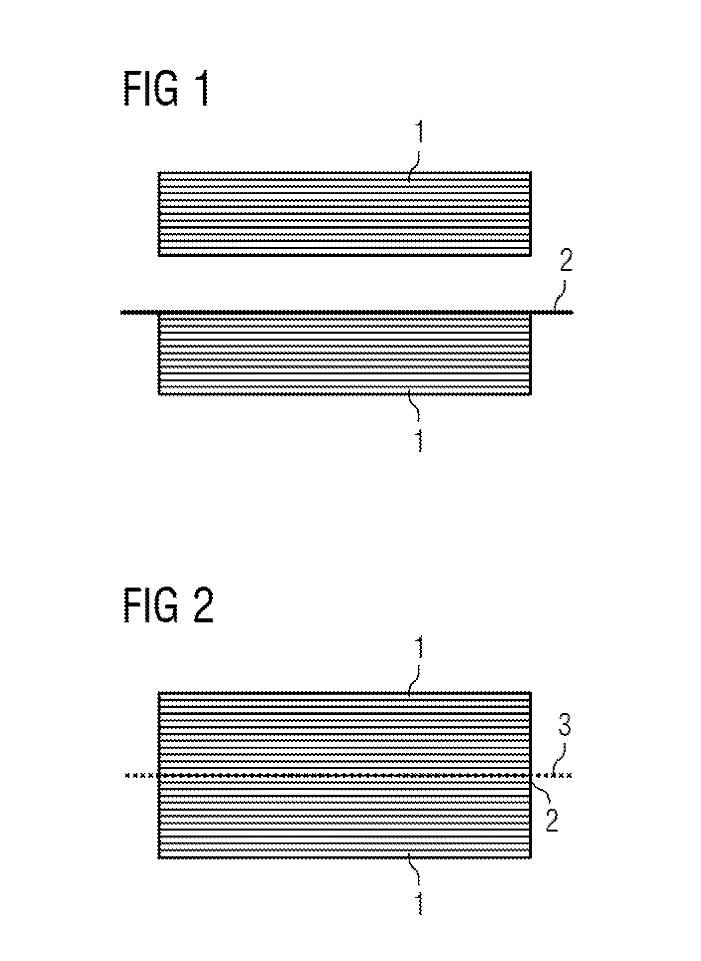
[0033]In the diagrams, like numbers refer to like objects throughout. Objects in the diagrams are not necessarily drawn to scale.

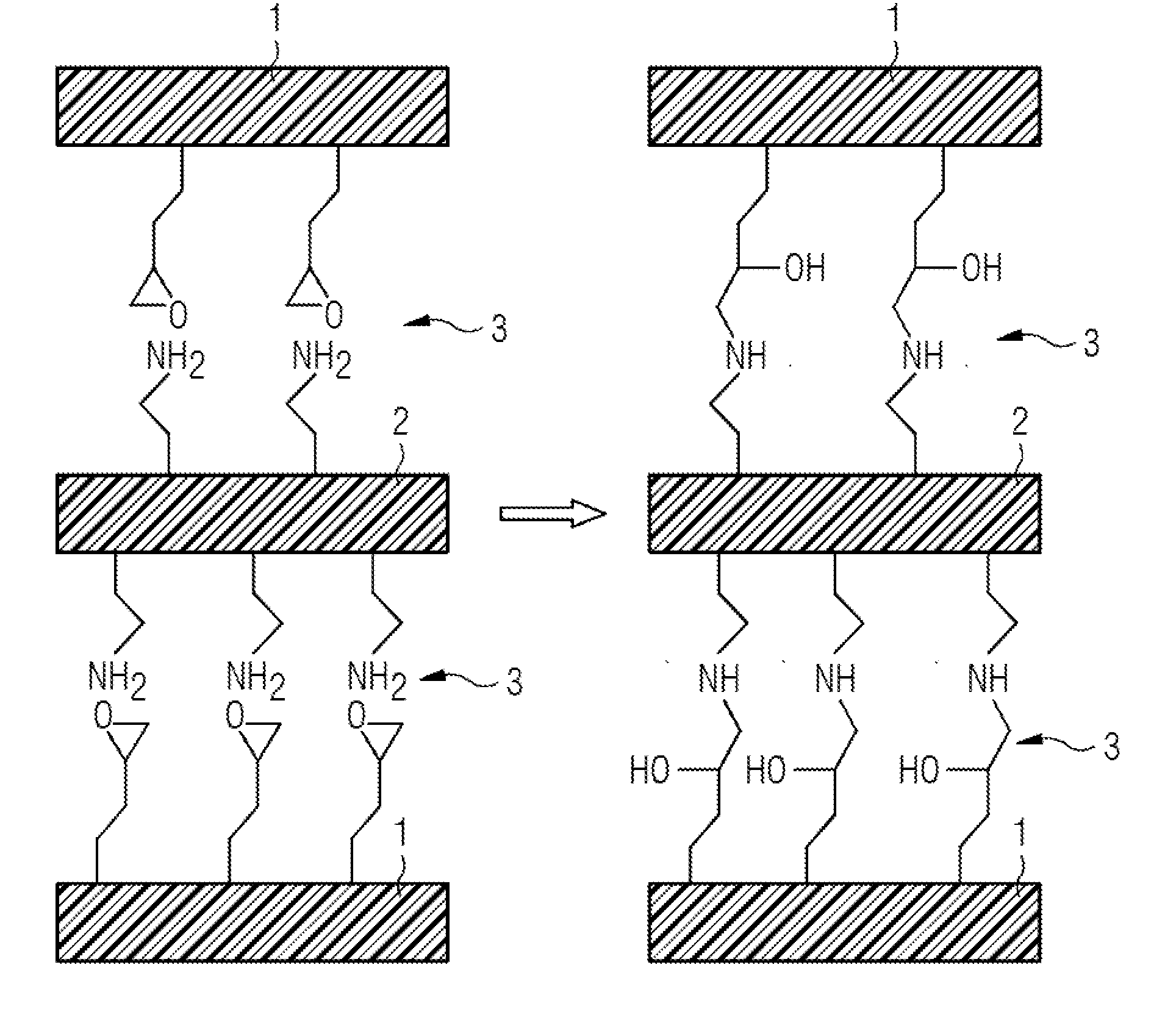
[0034]FIG. 1 shows a schematic view of the cross-section through a composite structure according to the invention in a state before assembling the thermoset resin containing elements 1 and the thermoplastic element 2. The composite structure comprises two thermoset resin containing elements 1 each composed of a number of fabric layers placed on each other in a parallel configuration to build up the two thermoset resin elements. The fabric layers may be formed by fabrics with or without a thermoset resin content. If the fabrics still contain a thermoset resin content, they are usually called prepregs. Otherwise, the fabric layers may be arranged together with the thermoplastic elements and then impregnated with thermoset resin. This is called resin injection process. Of course, both processes can be combined.

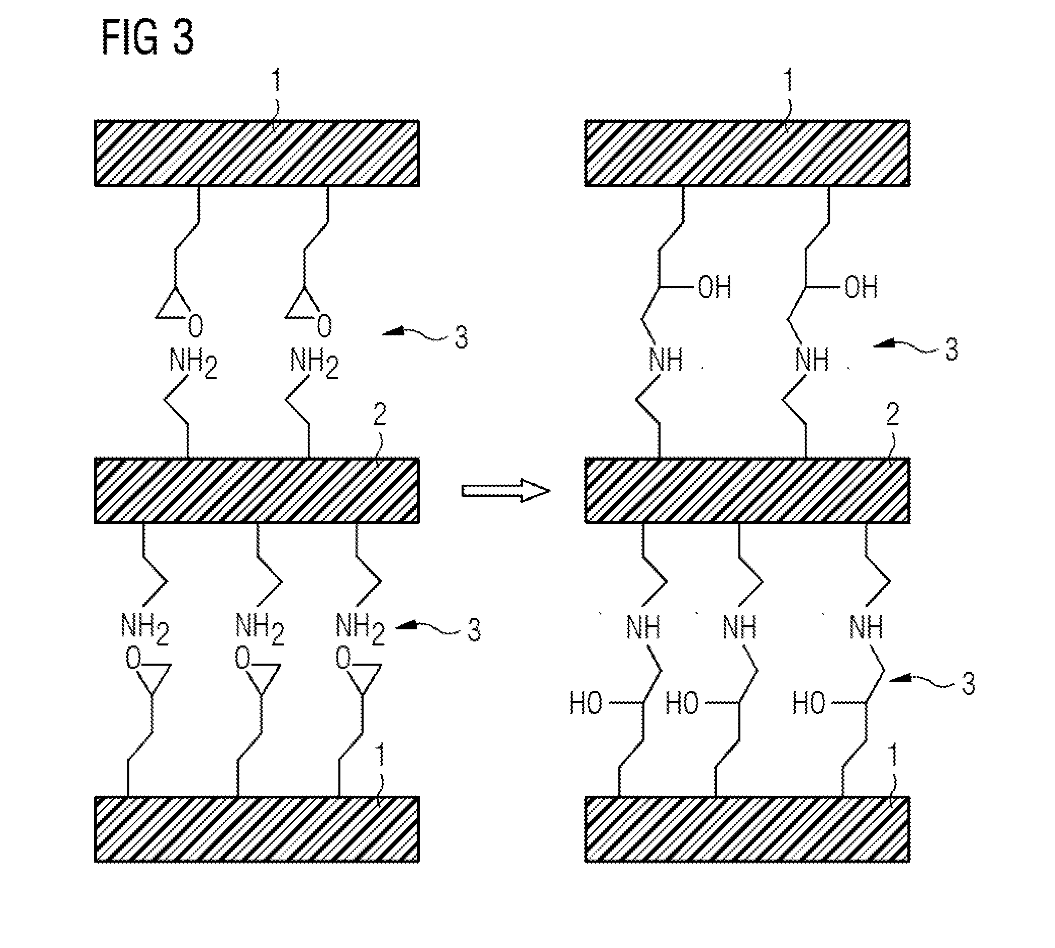
[0035]Between two thermoset resin containing elem...


PUM

PropertyMeasurementUnit
Structureaaaaaaaaaa

Abstract

A composite structure having a number of thermoset resin containing elements and a number of thermoplastic elements and at least one interface between the thermoset resin containing elements and the thermoplastic elements is provided. The thermoset resin containing elements and the thermoplastic elements have functional groups at the interface which bond to each other when the composite structure is cured and the functional groups are independently selected from amines, carboxylic acids, acid anhydrides, oxiranes, and derivatives thereof in their non-bonded condition. Additionally, a blade having such a composite structure is provided.

Description


Claims


Application Information

Patent Timeline
Owner SIEMENS GAMESA RENEWABLE ENERGY AS
Why Eureka
Try Eureka