Ornamental Attachment Device
- Summary
- Abstract
- Description
- Claims
- Application Information
AI Technical Summary
Benefits of technology
Problems solved by technology
Method used
Image

Examples
Embodiment Construction
[0005]The invention herein has been developed with the aim of providing an ornamental attachment device that resolves the aforementioned drawbacks, providing, in addition, other additional advantages that will become apparent from the description appended hereinafter.
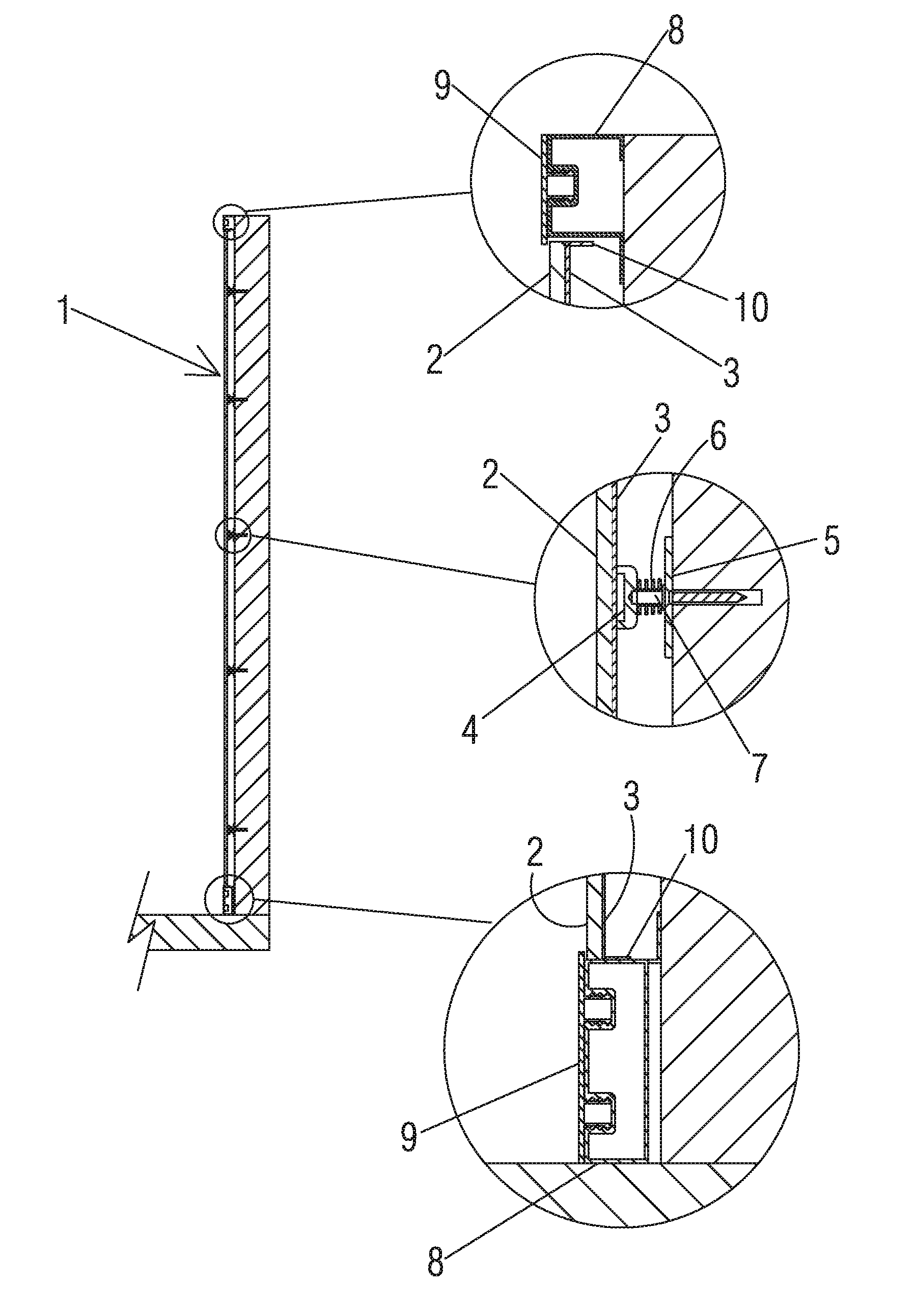
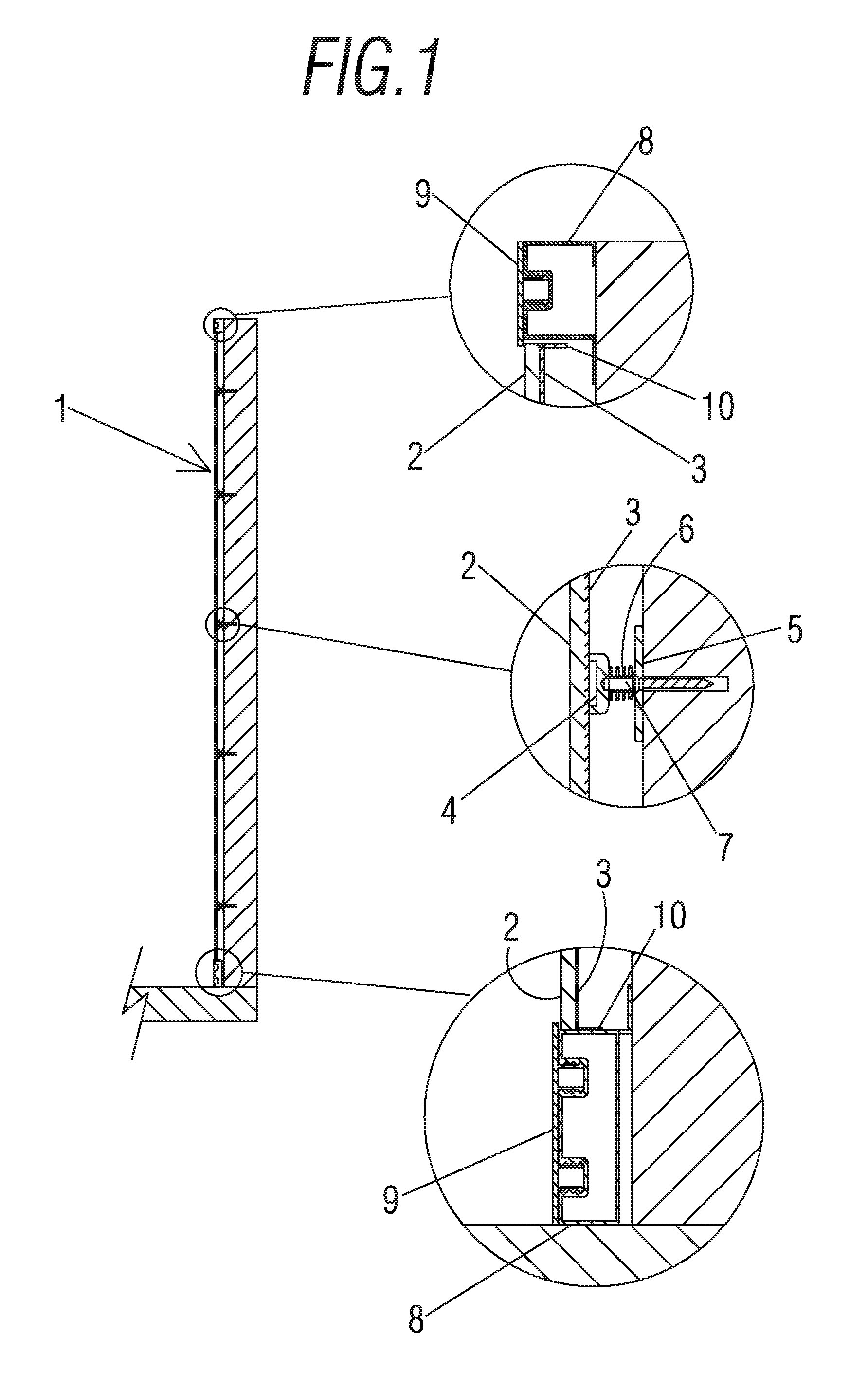
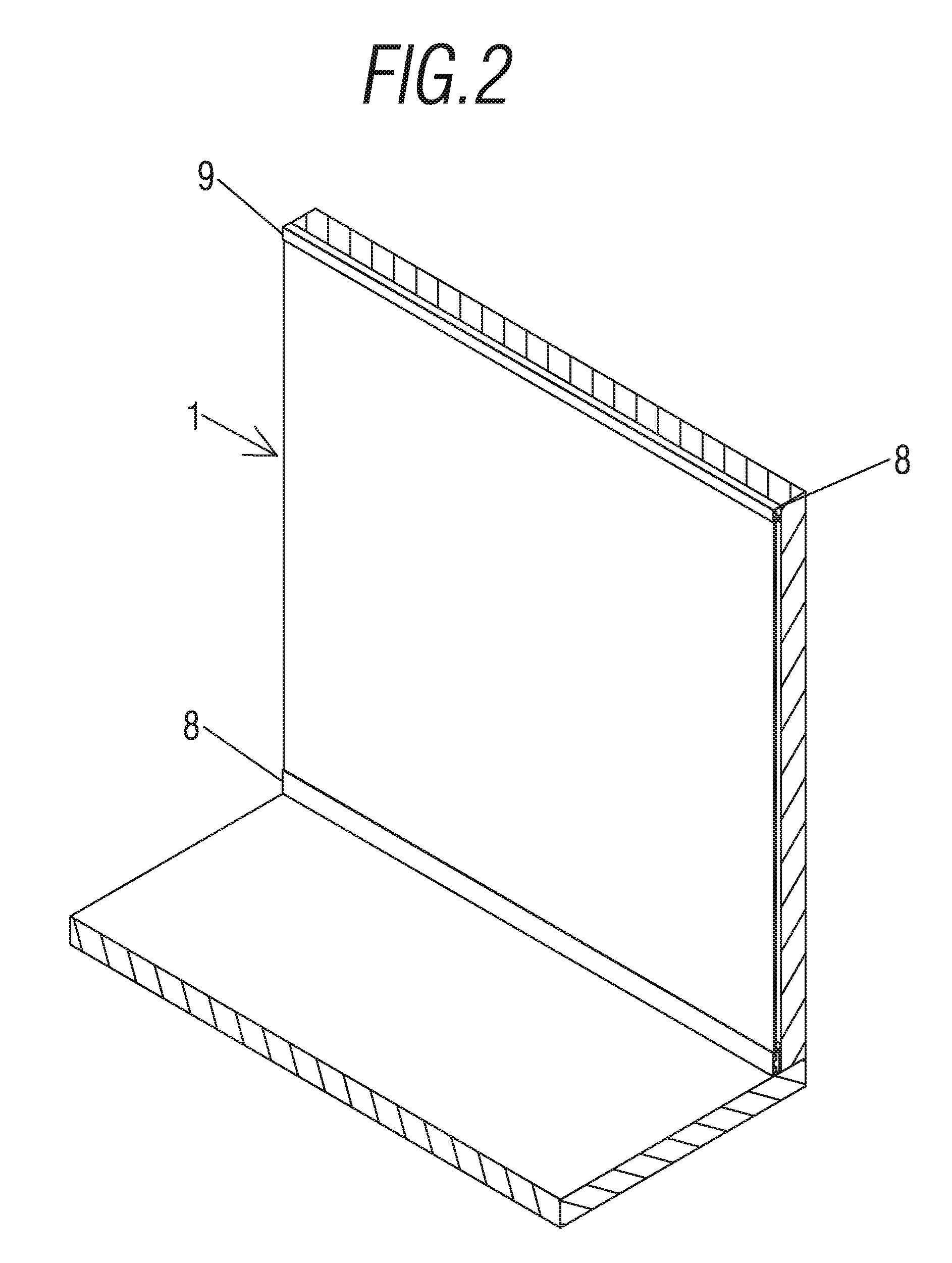
[0006]It is therefore an object of this invention to provide an ornamental attachment device that can be used in particular for flat surfaces, which is characterised in that it comprises a main body that has at least one ornamental sheet and one metal sheet joined to each other on one of the sides thereof, said main body being joined in a detachable manner to magnetic attachment means arranged on a surface to be decorated, support means fixed to the surface to be decorated having being provided on the ends of the main body such that said main body remains locked in position.
[0007]Thanks to these characteristics, an ornamental attachment device is achieved that can be easily and quickly installed that requires no buildin...
PUM
 Abstract
Description
Claims
Application Information
 - Generate Ideas
- Intellectual Property
- Life Sciences
- Materials
- Tech Scout
- Unparalleled Data Quality
- Higher Quality Content
- 60% Fewer Hallucinations
Browse by: Latest US Patents, China's latest patents, Technical Efficacy Thesaurus, Application Domain, Technology Topic, Popular Technical Reports.
© 2025 PatSnap. All rights reserved.Legal|Privacy policy|Modern Slavery Act Transparency Statement|Sitemap|About US| Contact US: help@patsnap.com