Two stage force multiplier tin snips

a force multiplier and snip technology, applied in the field of snips, can solve the problems of inability to adjust the handle, the operation of large tools may become overly cumbersome and inoperable, and the amount of physical input force of snips or shears intended to cut harder materials may be unacceptably large, so as to facilitate the inversion of the handle

Active Publication Date: 2014-10-09
I D L TOOLS INT
View PDF9 Cites 17 Cited by
  • Summary
  • Abstract
  • Description
  • Claims
  • Application Information

AI Technical Summary

Benefits of technology

[0011]Alternatively, the longitudinal location of the cutting blade axis or the handle axis may be changeable to adjust the mechanical advantage. In one embodiment, the cutting blade axis slidingly resides within a slot formed intermediate the cutting blades and the tangs. Sliding the cutting blade axis from a first position relatively closer to the tangs to a second position relatively closer to the cutting blades, effectively increases the force multiplier. Alternatively, the handle axis slidingly resides within a slot formed in each respective handle. Sliding the handle axis from a first position relatively closer to the handle ends to a second position relatively closer to the cutting blades, also effectively increases the mechanical advantage.
[0014]In another embodiment, the handles of the tin snips may invert to a compact position. In this embodiment, the tin snips include a spring tensioned between the tangs for biasing the tin snips in an open position. Handle inversion may be facilitated by a pair of handle axes interconnected by a coupler or by means of the pins as slidingly engaged to corresponding angular slots formed in the respective handles. The handle axes or angular slots provide the necessary rotational movement such that the handles are capable of rotating to an inverted position relative to the tangs and cutting blades.

Problems solved by technology

Even so, snips or shears intended to cut harder materials may require unacceptably large amounts of physical input force.
Or, alternatively, operation of large tools may become overly cumbersome and inoperable due to the long and bulky handle size.

Method used


Image

  • Two stage force multiplier tin snips
  • Two stage force multiplier tin snips
  • Two stage force multiplier tin snips

Examples


Embodiment Construction

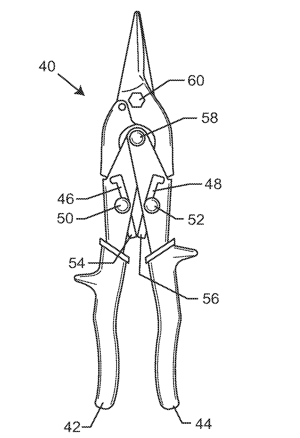
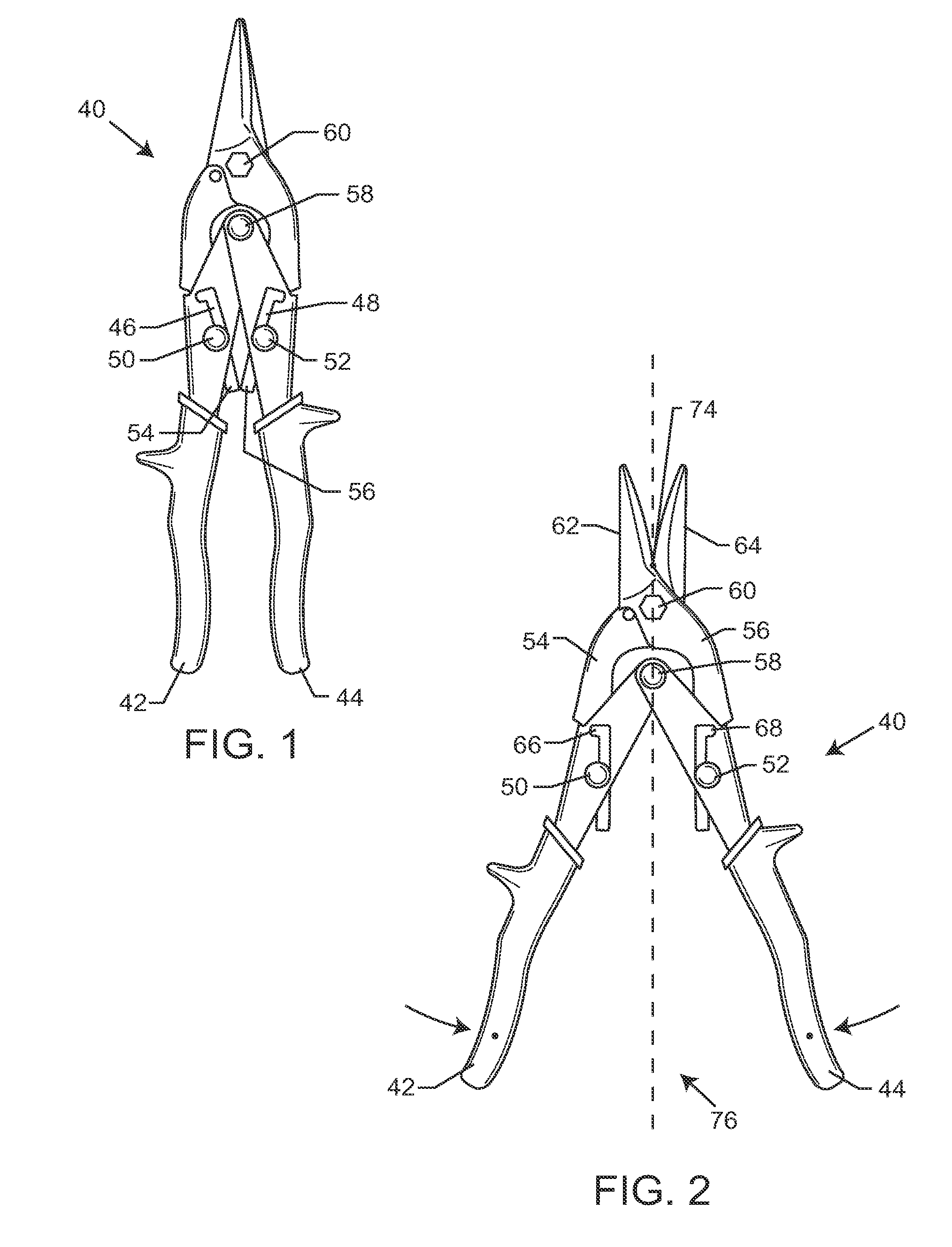
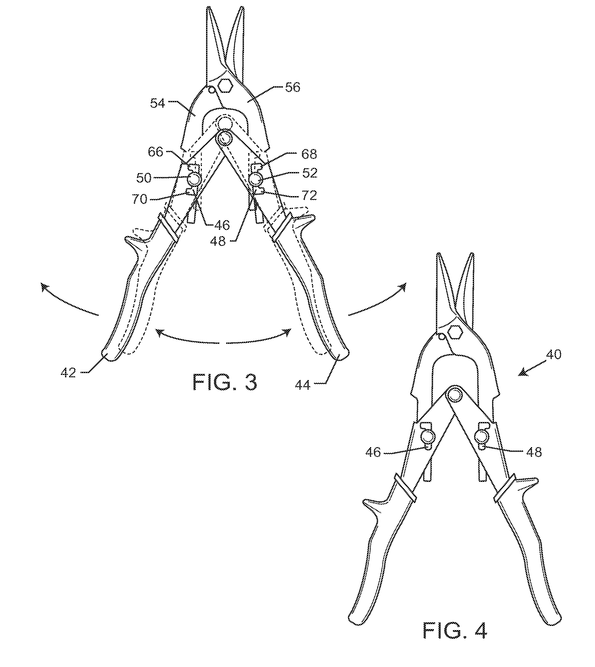
[0066]As shown in the exemplary drawings for purposes of illustration, the present disclosure for tin snips is referred to generally by the reference numeral 40. Turning now to the representative figures in the specification, FIG. 1 illustrates the tin snips 40 having a set of pivotably connected handles 42, 44, each having a slot 46, 48 formed therein. The slots 46, 48 are each adapted to receive a pair of pins 50, 52 which are secured to a pair of blade tangs 54, 56. The handles 42, 44 move relative to one another about a common handle axis point 58. The pair of blade tangs 54, 56 are correspondingly configured to pivot about a base axis point 60 that separates the blade tangs 54, 56 from a pair of cutting blades 62, 64 (shown best in FIG. 2). The cutting blades 62, 64 are shown in FIG. 1 in closed form. In this embodiment, the slots 46, 48 are formed in the handles 42, 44 and are configured to have the tin snips 40 operate in a compact position, as shown in

[0067]FIG. 1, or an ext...


PUM

PropertyMeasurementUnit
forceaaaaaaaaaa
mechanical advantageaaaaaaaaaa
constant forceaaaaaaaaaa

Abstract

Two-stage force multiplier tin snips are provided which have a pair of cutting blades and associated tangs, both being pivotable about a cutting axis. Each respective tang is coupled to a pair of handles by a pair of respective tang pins. The handles are pivotably attached to one another about an adjustable handle axis. The handle axis is adjustable between an upper position and a lower position to provide a mechanism for changing a force multiplier of the cutting blades. The handle axis may be a sliding axis disposed in longitudinal slots on the handles. The handle axis may also be upper and lower fixed pins that are slidable in lateral slots.

Description

RELATED APPLICATION[0001]This application is a continuation-in-part of U.S. application Ser. No. 11 / 937,113 filed Nov. 8, 2007 (now U.S. Pat. No. 8,739,415), which claims the benefit of U.S. Provisional Application Ser. No. 60 / 865,612, filed Nov. 13, 2006.BACKGROUND OF THE INVENTION[0002]The present disclosure relates to tin snips. More particularly, the invention relates to tin snips having a two-stage force multiplier capable of changing the mechanical advantage.[0003]Snips or shears are among the most commonly used hand tools in industries ranging from sheet metal formation to gardening. Conventional snips or shears generally comprise an upper and lower cutting blade, each having elongated handles extending therefrom and attached thereto. The cutting blades are configured to pivot around a single axis point that separates the cutting blades from the handles. The cutting motion is activated by applying a constant force to the exterior of the handles. This exterior force effectivel...

Claims


Application Information

Patent Timeline
Patent Type & Authority Applications(United States)
IPC IPC(8): B26B13/26
CPCB26B13/26A01G3/02A01G3/021B23D29/026
Inventor CARMICHAEL, ERIC B.SEBER, BRETT P.TORN, WESLEY JAMES
Owner I D L TOOLS INT
Why Eureka
Try Eureka