Elastic retaining arrangement for jointed components and method of reducing a gap between jointed components

a technology of elastic retaining arrangement and jointed components, applied in the field of components, can solve the problems of undesirable effects, large and varied gaps, unsatisfactory fit, etc., and achieve the effect of reducing the gap between jointed components

Active Publication Date: 2014-10-09
GM GLOBAL TECH OPERATIONS LLC
View PDF3 Cites 28 Cited by
  • Summary
  • Abstract
  • Description
  • Claims
  • Application Information

AI Technical Summary

Benefits of technology

[0004]In another exemplary embodiment, a method of reducing a gap between jointed components is provided. The method includes positioning a first interface edge of a first component in close proximity with a second interface edge of a second component. The method also includes engaging at least one elastically deformable protrusion extending from a first main body portion of the first component with at least one plurality of aperture defined by an aperture wall

Problems solved by technology

As a result, occurrence of significant positional variation between the mated components is possible, which may contribute to the presence of undesirably large and varying gaps and otherwise poor fit.
The clearance between the align

Method used


Image

  • Elastic retaining arrangement for jointed components and method of reducing a gap between jointed components
  • Elastic retaining arrangement for jointed components and method of reducing a gap between jointed components
  • Elastic retaining arrangement for jointed components and method of reducing a gap between jointed components

Examples


Embodiment Construction

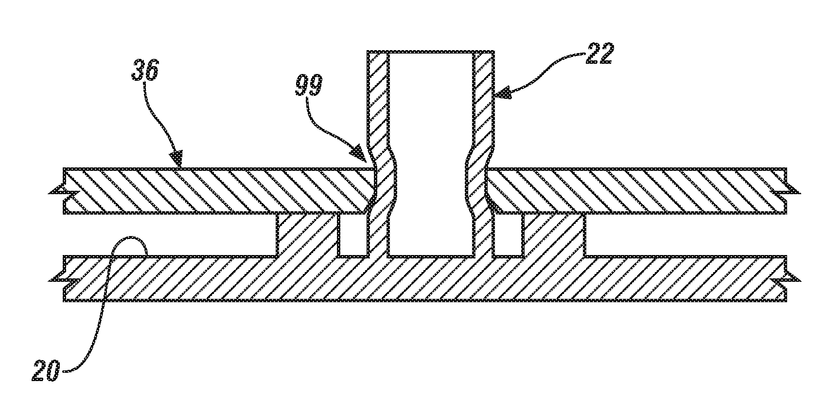
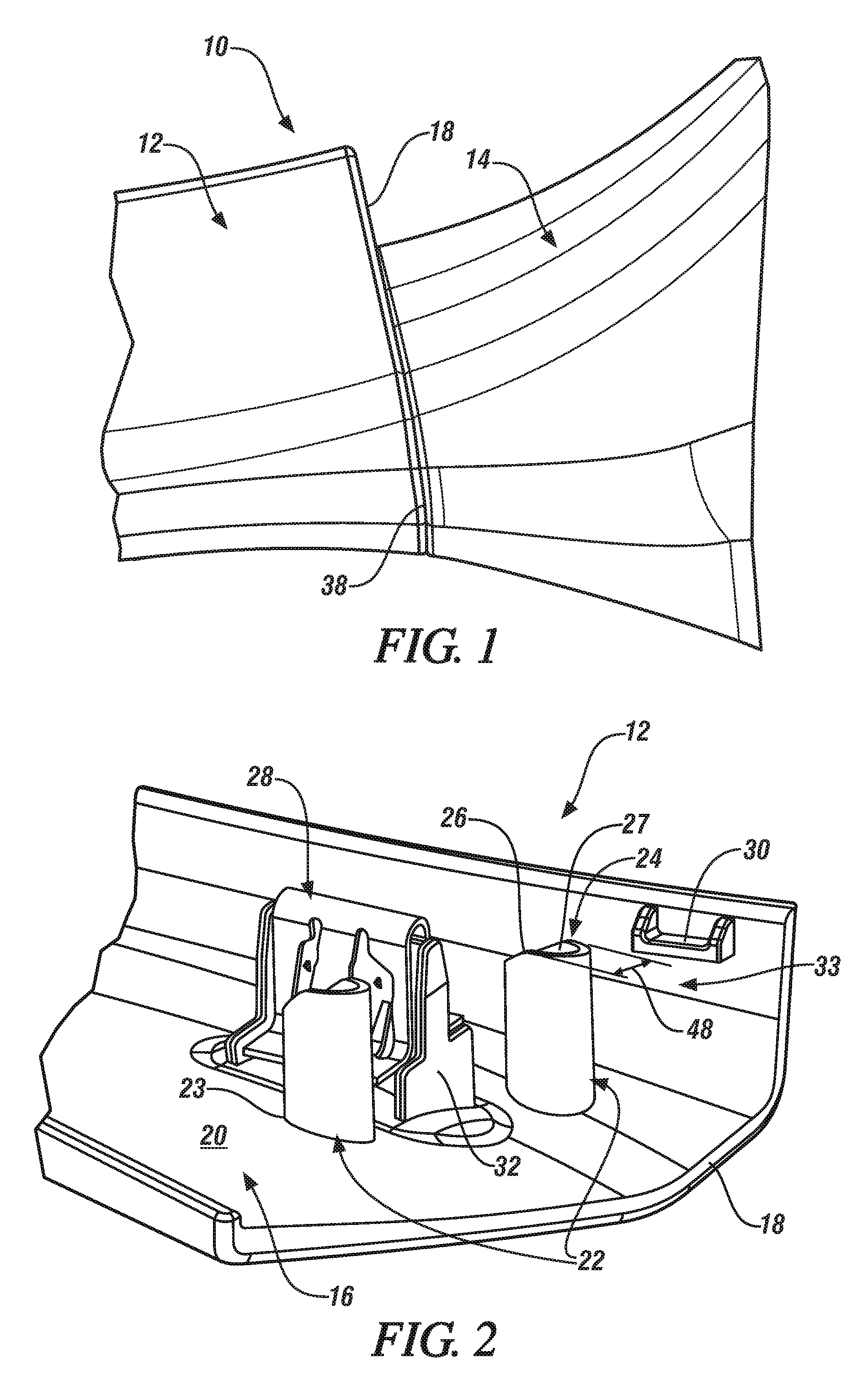
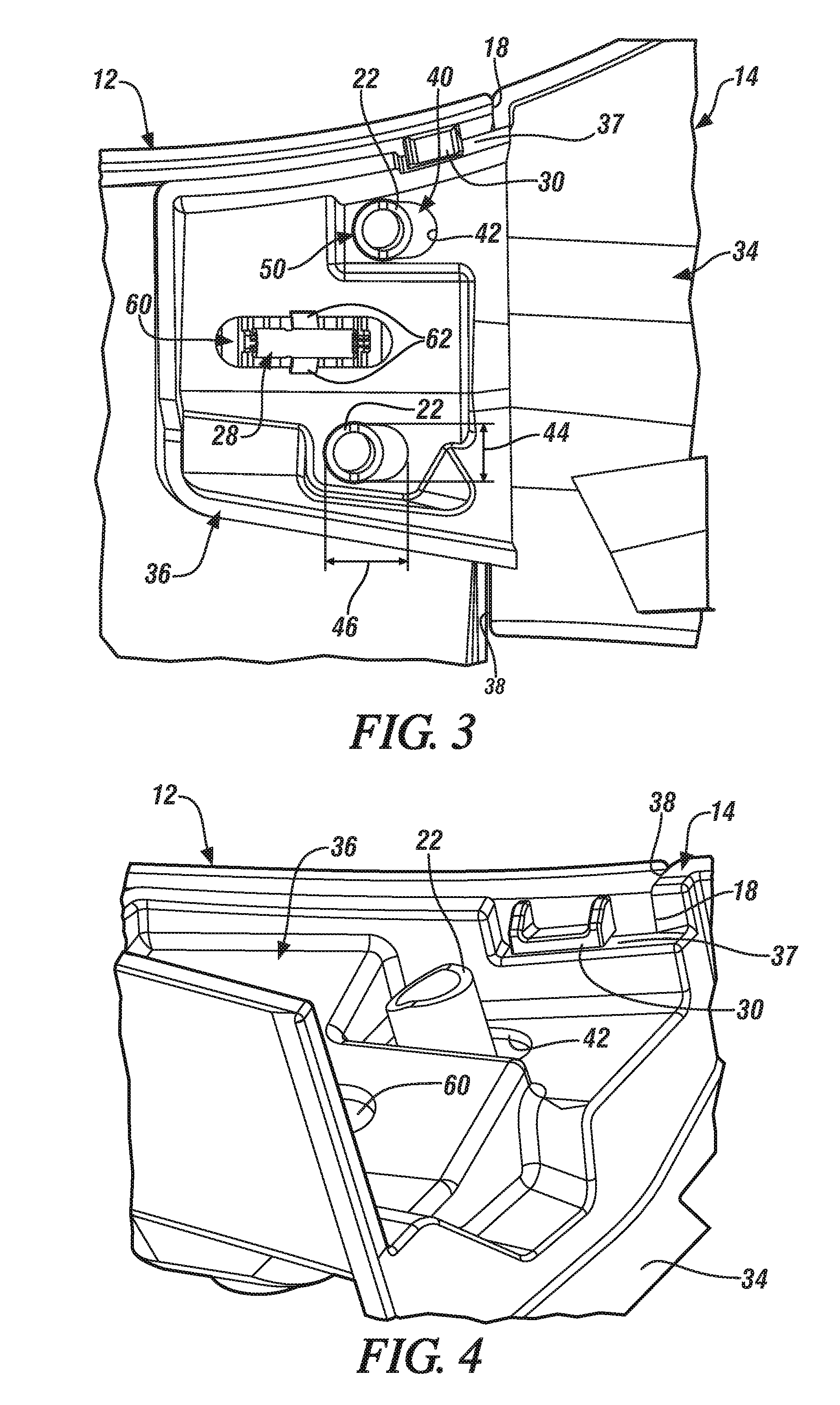
[0017]Referring to FIG. 1, a jointed assembly 10 is illustrated. The jointed assembly 10 comprises components configured to be engaged or mated with each other, such as a first component 12 and a second component 14. The jointed assembly 10 may be associated with numerous applications and industries, such as home appliance and aerospace applications, for example. In one embodiment, the jointed assembly 10 is employed in a vehicle, such as an automobile. In an automobile embodiment, the jointed assembly 10 may comprise a carpet retainer and hinge pillar or “B” pillar trim that is located proximate a door opening and a floorboard. As will be appreciated from the description herein, embodiments of the jointed assembly 10 may be used in any application that benefits from a reduction or elimination of a gap at a joint between mated or engaged components.

[0018]Referring to FIG. 2, the first component 12 includes a first main body portion 16 that extends to a terminal location defined by a...


PUM


Abstract

A retaining arrangement includes a first component having a first main body portion and a first interface edge. Also included is a second component operatively coupled to the first component, the second component comprising a second main body portion, a second interface edge in contact with the first interface edge, and an end portion in an overlapped configuration with the first main body portion of the first component. Further included is an aperture defined by an aperture wall and extending through the end portion of the second component. Yet further included is an elastically deformable protrusion extending away from the first main body portion of the first component, the elastically deformable protrusion configured to fittingly engage the aperture proximate an end region of the aperture wall, wherein the elastically deformable protrusion is formed of an elastically deformable material and configured to elastically deform upon engagement with the aperture wall.

Description

FIELD OF THE INVENTION[0001]The invention relates to components which are to be mated together, and more particularly to an elastic retaining arrangement for jointed components, as well as a method of reducing a joint gap between jointed components.BACKGROUND[0002]Currently, components which are to be mated together in a manufacturing process are subject to positional variation based on the mating arrangements between the components. One common arrangement includes components mutually located with respect to each other by 2-way and / or 4-way male alignment features; typically undersized male structures which are received into corresponding oversized female alignment features such as apertures in the form of openings and / or slots. Alternatively, double-sided tape, adhesives or welding processes may be employed to mate parts. Irrespective of the precise mating arrangement, there is a clearance between at least a portion of the alignment features which is predetermined to match anticipa...

Claims


Application Information

Patent Timeline
IPC IPC(8): B62D27/02F16B5/00
CPCF16B5/0032B62D27/023F16B5/0056F16B5/0657F16B19/002F16B2200/10
Inventor MORRIS, STEVEN E.KUSHNER, JAMES M.ENYEDY, VICTORIA L.LAWALL, JENNIFER P.OGONEK, PIOTR J.
Owner GM GLOBAL TECH OPERATIONS LLC
Why Eureka
Try Eureka