Wearable Reflective Device

Active Publication Date: 2014-10-09
CRANE IP
View PDF8 Cites 8 Cited by
  • Summary
  • Abstract
  • Description
  • Claims
  • Application Information

AI Technical Summary

Benefits of technology

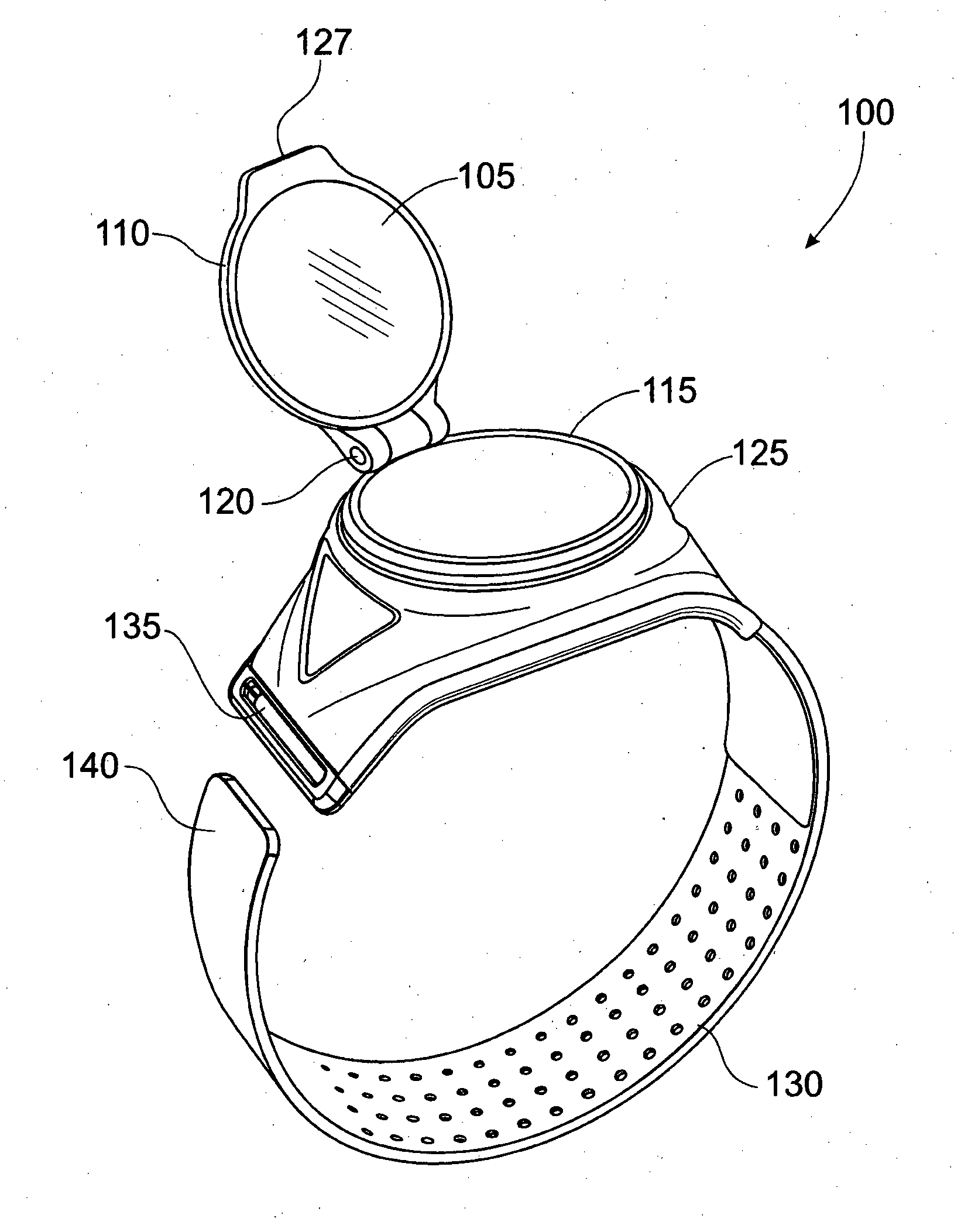
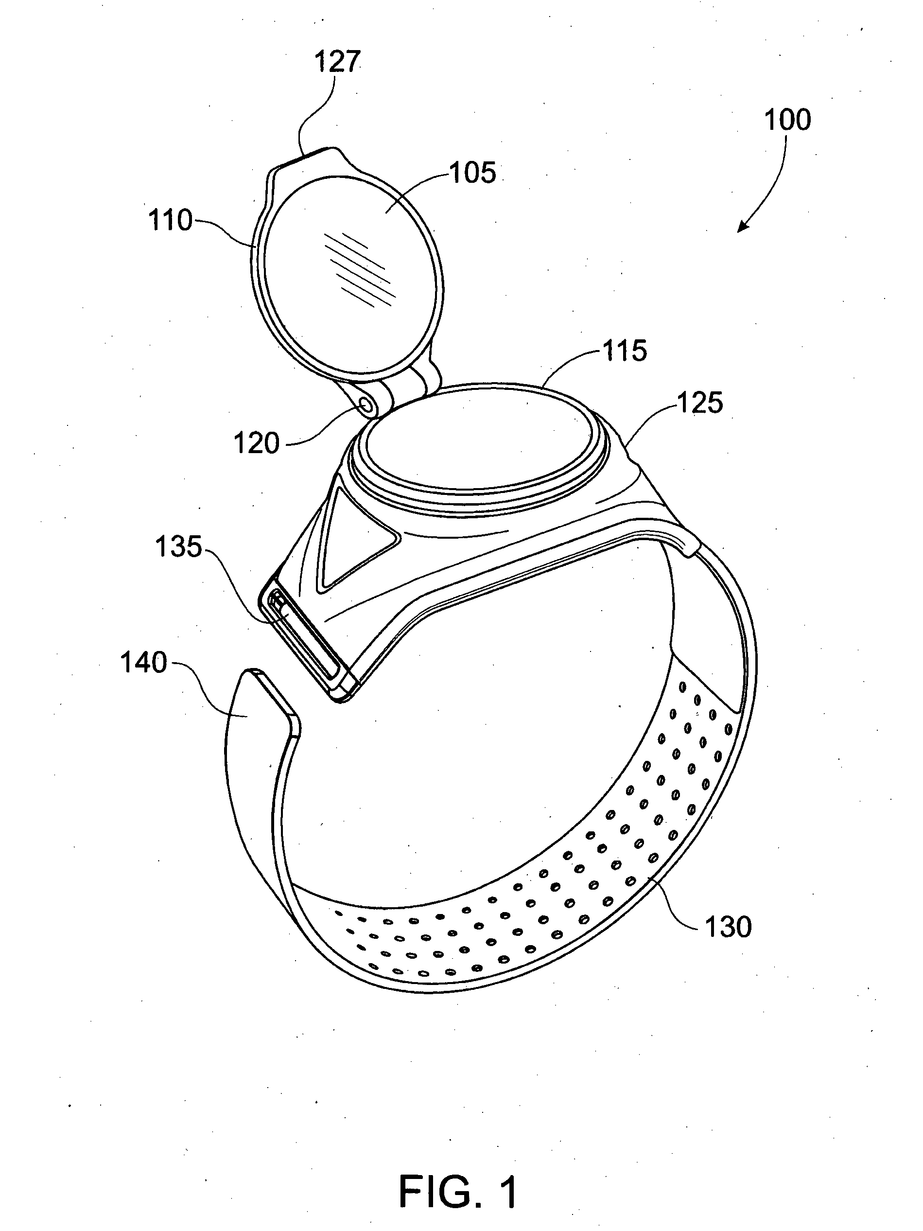
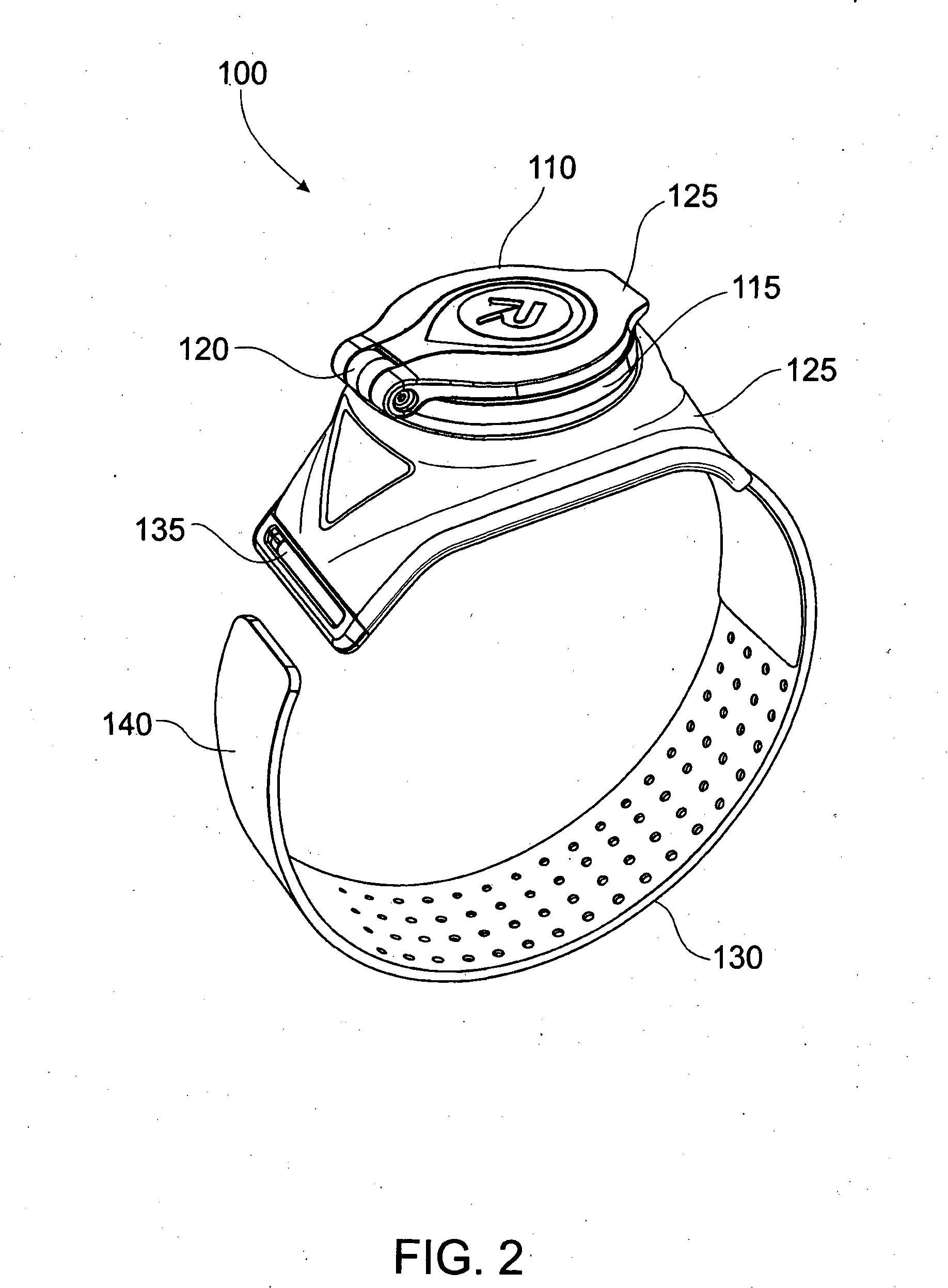
The patent describes a coupling member that connects a mirror to a base. This coupling member allows the mirror to move between two positions. In the first position, the mirror protects the reflective surface and in the second position, the surface is exposed. The technical effect of this design is that it allows for easy movement and protection of the mirror's reflective surface.

Problems solved by technology

Riding to work in city environments, in traffic and on busy pathways can, however, be hazardous.
Firstly, a cyclist's vision is completely taken off the path on which they are travelling.
This can, for example, increase the risk of frontal collisions.
Secondly, it is difficult for a cyclist to maintain a straight riding position as the cyclist is typically unable to rotate his or her head 180 degrees without shoulder movement.
A problem with handlebar mounted mirrors is that they are unsteady and are blurred by vibrations of the bicycle, for example on a rough surface such as a typical road.
A further problem with handlebar mounted mirrors, is that they are bulky because of the extended arm, and accordingly are both prone to damage and prone to cause injury to the cyclist and / or others in the event of an accident.
A problem with such helmet mounted mirrors is that they require the use of certain types of helmets and / or require modification to a helmet.
Additionally, the helmet mounted mirrors can impair movement of a cyclist and cause further injury in case of an accident.

Method used


Image

  • Wearable Reflective Device
  • Wearable Reflective Device
  • Wearable Reflective Device

Examples


Embodiment Construction

[0043]Embodiments of the present invention comprise wearable reflective devices. Elements of the invention are illustrated in concise outline form in the drawings, showing only those specific details that are necessary to the understanding of the embodiments of the present invention, but so as not to clutter the disclosure with excessive detail that will be obvious to those of ordinary skill in the art in light of the present description.

[0044]In this patent specification, adjectives such as first and second, left and right, front and back, top and bottom, etc., are used solely to define one element or method step from another element or method step without necessarily requiring a specific relative position or sequence that is described by the adjectives. Words such as “comprises” or “includes” are not used to define an exclusive set of elements or method steps. Rather, such words merely define a minimum set of elements or method steps included in a particular embodiment of the pres...


PUM


Abstract

A wearable reflective device. The wearable reflective device includes a mirror, a base and a strap. The strap is attached to the base for securing the device to a user. The mirror is connected to the base by a pivotal element and a rotational element, wherein the pivotal element is configured to allow the mirror to pivot along a first plane, the rotational element configured to allow the mirror and pivotal element to rotate in a second plane. The first plane is substantially orthogonal to the second plane.

Description

FIELD OF THE INVENTION[0001]The present invention relates to safety devices, and in particular, although not exclusively, to a wearable reflective device.BACKGROUND TO THE INVENTION[0002]Cycling is a popular sport and pastime, and cycling as a means of transportation has become popular due to environmental and financial factors. Riding to work in city environments, in traffic and on busy pathways can, however, be hazardous.[0003]A cyclist can improve his or her safety by having knowledge of their surroundings and by predicting behaviour of others. This can include being aware of vehicles or other cyclists that are approaching them from behind. Similarly, when racing, knowledge of a competitor's position can form an integral part of a cycling strategy.[0004]It is thus common for cyclists to periodically turn their heads to look behind them. However looking back in this way has several disadvantages. Firstly, a cyclist's vision is completely taken off the path on which they are travel...

Claims


Application Information

Patent Timeline
IPC IPC(8): A45D42/06
CPCA45D42/06A45D42/12B62J29/00G02B7/002G02B7/1822
Inventor CRANE, RAYMOND PHILLIP
Owner CRANE IP
Why Eureka
Try Eureka