Vertical lift storage system and a method of operating a lift

a vertical lift and storage system technology, applied in the direction of electric digital data processing, loading/unloading, instruments, etc., can solve the problems of unfavorable sideways stability, rack damage, and high cost, and achieve the effect of gentle handling and improved sideways stability

Active Publication Date: 2014-10-09
EFFIMAT STORAGE TECH
View PDF19 Cites 17 Cited by
  • Summary
  • Abstract
  • Description
  • Claims
  • Application Information

AI Technical Summary

Benefits of technology

[0026]Thereby the first transportation means are configured as a lifting type which is lowered slightly below a load unit to leave the load while it slides below or is slightly raised to lift a load unit and thereby to insert or withdraw a load unit. This configuration can give a gentle handling of the load units since they are only to a limited extent exposed to drag and thus frictional wear.
[0027]In some embodiments, the first transportation means at a given section is configured with one telescopic arm with a respective support face to carry (i.e. insert or withdraw) one load item at a time. In other embodiments, two or more support faces may be moved by respective telescopic arms operated synchronously to transport a (single) load item. For instance two arms are moved synchronously to transport one load item. Thereby the first transport means have an improved sideways stability. Such two or more arms can be operated synchronously by driving them with common drive means (such as a motor). Alternatively, by driving their respective drive means synchronously.

Problems solved by technology

This storage rack suffers from problems related to deflection of the elevator carrying the slide since the elevator spans a greater length.
Low deflection is desired since it gives a precise, reliable and thus fast mechanical system, but it comes at a very high cost and with a very heavy construction.
Thus an undesired trade-off comes with this storage rack and its transport device.
Further, this prior art storage rack suffers from a lack of efficiency in bringing the containers forth and back from their storage positions.

Method used


Image

  • Vertical lift storage system and a method of operating a lift
  • Vertical lift storage system and a method of operating a lift
  • Vertical lift storage system and a method of operating a lift

Examples


Embodiment Construction

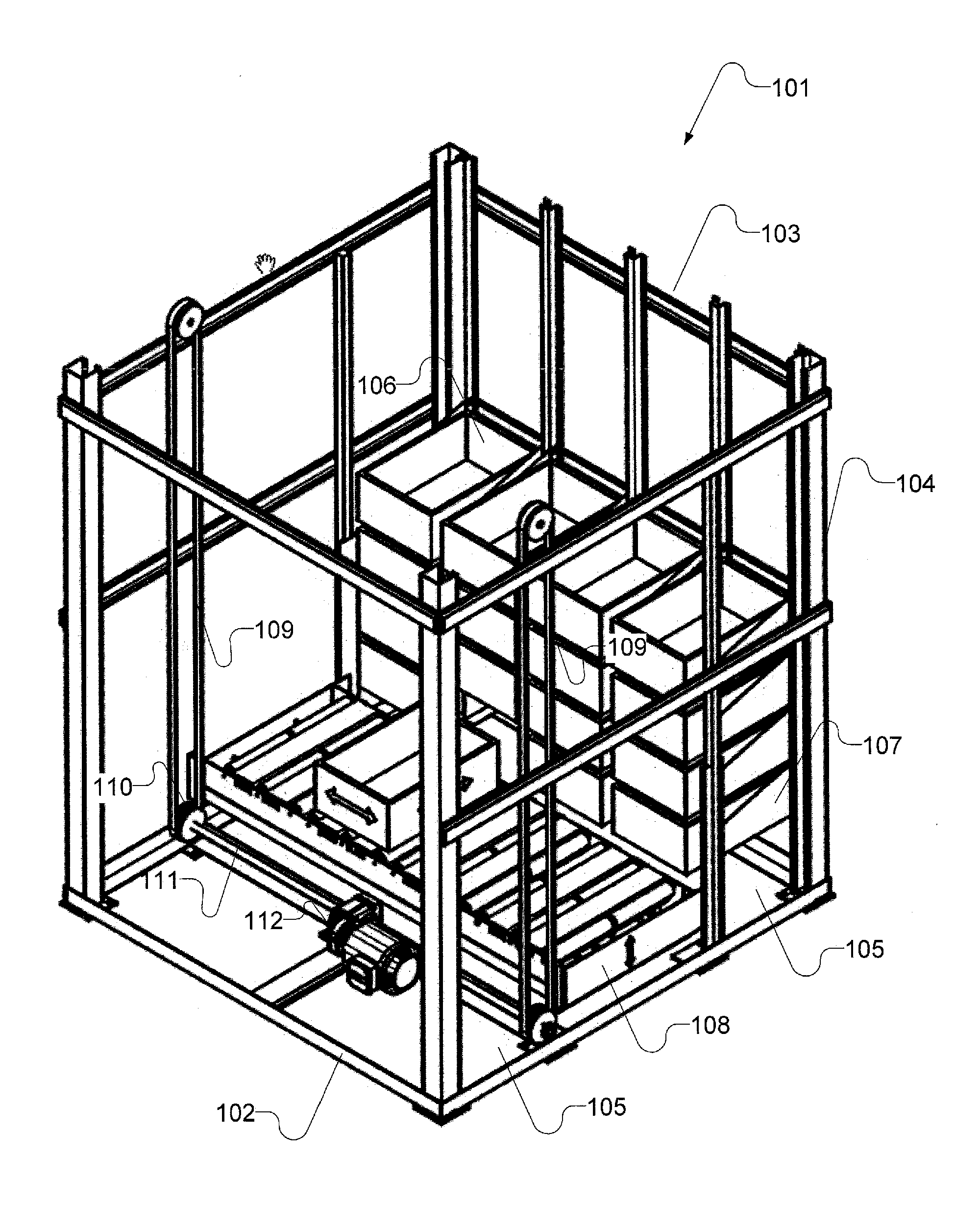
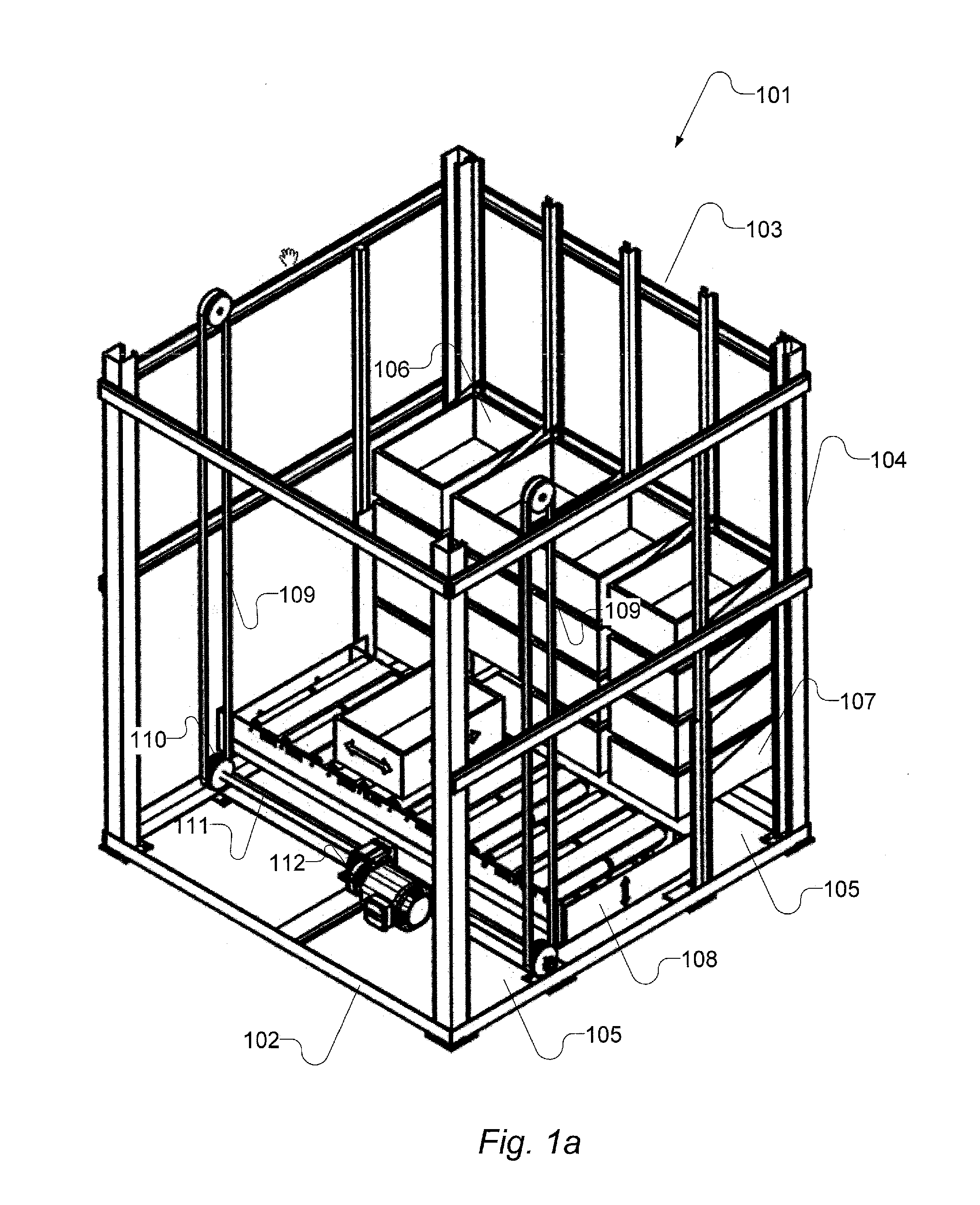
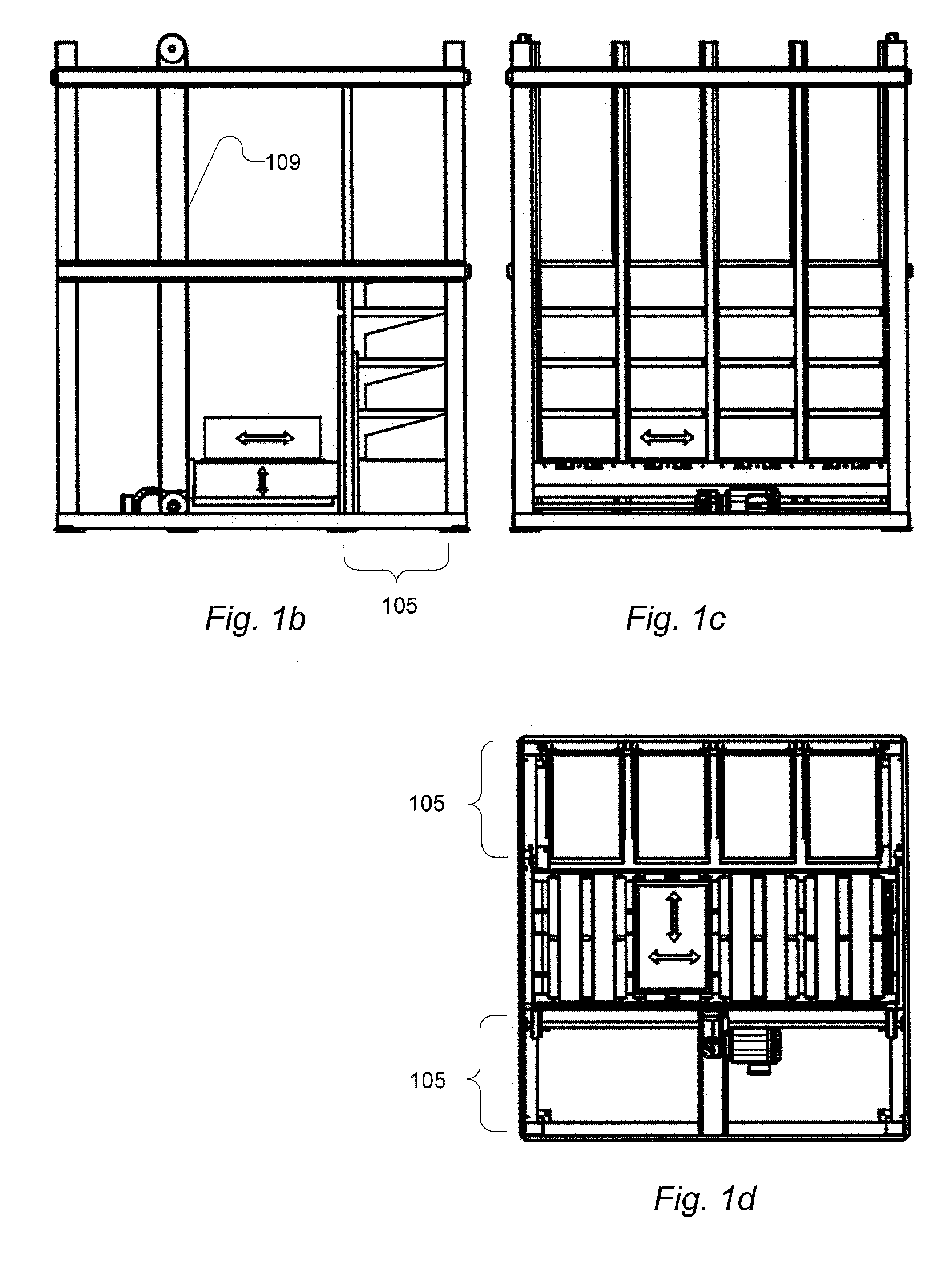
[0090]FIG. 1 shows a vertical lift storage system. FIG. 1a is a perspective view; FIG. 1b is a first side view; FIG. 1c is a second side view and FIG. 1d is a top view.

[0091]The vertical lift storage system is generally designated by reference numeral 101. It comprises a frame structure 102 with vertical and horizontal metal profiles 103; 104. The system 101 comprises a storage rack section 105 that stores some load items 106. The storage rack 105 comprises brackets 107 supporting the load items 106. The storage rack 105 is configured to store the load items in straight columns at equally spaced levels. The storage rack 105 is disposed on either side of an elevator shaft wherein the carrier structure 108 is upwardly and downwardly movable. Only the distant rack section contains load items in this view.

[0092]A hoist mechanism configured to move the carrier structure 108 up and down and to hold it in at a specified vertical level comprises a first and second belt 109 attached to the c...


PUM


Abstract

There is provided a vertical lift storage system (101), comprising a storage rack (105) configured to store load units and a lift system with an upwardly and downwardly movable carrier structure (108), where the carrier structure (108) is configured to carry multiple load units at respective sections and with first transportation means configured to insert and withdraw respective load units into and from the storage rack. The system is characterized in that the carrier structure is configured with second transportation means to shift load units sideways on the carrier structure between its sections. In some embodiments the first transportation means comprises telescopic arms and the second transportation means comprises rollers. There is also provided a method of operating such a carrier structure in a vertical lift storage system,

Description

[0001]The present invention relates to a vertical lift storage system comprising a storage rack configured to store load units and a lift system with an upwardly and downwardly movable carrier structure. The carrier structure is also denoted a lift or an elevator within the technical area. The carrier structure is configured to carry multiple load units at respective sections and with first transportation means configured to insert and withdraw respective load units into and from the storage rack.[0002]Generally, a load item is known as a tote or a load supporting element, a box or a container. The particular type of load item is selected in dependence of what goods it is intended to store. Often the goods are pieces / elements or tubs or pots or parcels, but it may also be powder or liquids. A load item may be a box e.g. with a rectangular bottom, sides and an upward opening, it may be provided with a lid; or a tray with only slightly raised edges; or a substantially flat board or an...

Claims


Application Information

Patent Timeline
Patent Type & Authority Applications(United States)
IPC IPC(8): B65G1/06
CPCB65G1/06B65G1/0407B65G1/04B65G1/0478
Inventor LANGHOFF, TOMMY
Owner EFFIMAT STORAGE TECH
Why Eureka
Try Eureka