Conveying apparatus and method of conveying tampon applicators

a technology of conveying apparatus and tampon, which is applied in the direction of lighting and heating apparatus, charge manipulation, furniture, etc., can solve the problems of complicated separation, large space occupied by conveying belts, and damage to the side delimitation of tampon applicators, and achieves the effect of gentle handling of tampon applicators

Active Publication Date: 2021-09-23
RUGGLI PROJECTS AG
View PDF0 Cites 0 Cited by
  • Summary
  • Abstract
  • Description
  • Claims
  • Application Information

AI Technical Summary

Benefits of technology

[0007]It is therefore an object of the present invention to overcome at least one disadvantage of the prior art. In particular, the intention is to provide a conveying apparatus for tampon applicators and a method for conveying tampon applicators that complies with the exacting requirements of continuous assembly of tampon applicators and, in the process, permits gentle handling of the tampon applicators.

Problems solved by technology

The conveyor belts also take up a large space in the production lines.
In the case of high-quality materials, there is also the risk due to the side delimitations of the tampon applicators being damaged.
The separating on such conveyor belts has turned out to be complicated and error-prone.
An applicator oriented incorrectly may lead to the entire assembly unit shutting down.

Method used


Image

  • Conveying apparatus and method of conveying tampon applicators
  • Conveying apparatus and method of conveying tampon applicators
  • Conveying apparatus and method of conveying tampon applicators

Examples


Embodiment Construction

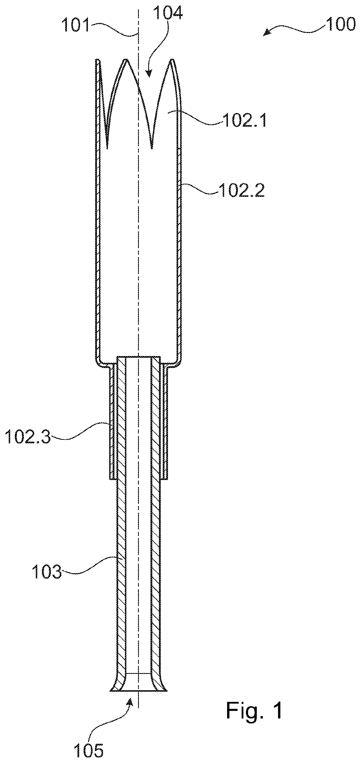
[0085]FIG. 1 shows by way of example a tampon applicator 100 as can be conveyed with the device according to the invention. The tampon applicator 100 is substantially constructed in two parts. It is composed of a tampon body and a plunger 103. The plunger 103 is arranged in the tampon applicator 100 in such a manner that it can be displaced along the longitudinal axis 101. The tampon applicator 100 has a distal head end 104 with a head opening. The proximal thread opening 105 of the plunger 103, which is configured as a small tube, lies opposite.

[0086]The tampon body is divided into three regions. Incised wings configured in the form of a petal 102.1 are located at the distal head end 104. Said wings run into the sleeve body 102.2, which defines a tampon cavity. The sleeve body 102.2 is directly adjoined by a gripping region 102.3 which, in the present example, also serves for guiding the plunger 103. The sleeve body 102 serves for receiving a tampon, wherein, in the current assembl...


PUM


Abstract

The present invention relates to a conveying apparatus for tampon applicators 100, having a first conveyor track 2, which comprises two transport belts 3.1, 3.2 which are arranged spaced apart from each other. The transport belts each have a bearing axis L1, L2. The conveying apparatus according to the invention furthermore has a first conveyor drive 4 for driving at least one of the two spaced-apart transport belts 3.1, 3.2, and transport belts which are arranged spaced apart from each other in such a manner that a tampon applicator 100 which is to be conveyed rests on the two transport belts in an intermediate space D between the transport belts. The bearing axes L1, L2 of the transport belts 3.1, 3.2 are arranged parallel; in particular in the case of transport belts having the same conveying direction F. The present invention furthermore relates to a method of conveying tampon applicators.

Description

[0001]The present invention relates to a conveying apparatus for tampon applicators, and to a method of conveying tampon applicators, in particular in a production line for tampons with applicators; all according to the preamble of the independent patent claims.TECHNOLOGICAL BACKGROUND[0002]Tampon applicators are generally tubular insertion aids composed of plastic for tampons. In their simplest construction, they have a sleeve body with a distal opening through which the tampon is released after being placed into the body orifice. The tampon is ejected by means of a proximally applied plunger. Pushing of the plunger into the sleeve body presses the tampon contained in the latter through said distal opening. More developed forms have a rounded distal head end which is provided with incisions which open in the manner of a flower when the tampon is pressed out. Recessed grips or ribbed portions also belong nowadays to the standard configurations for facilitating practicality. The plun...

Claims


Application Information

Patent Timeline
Patent Type & Authority Applications(United States)
IPC IPC(8): B65G47/53B65G15/10B65G49/00B65G47/74
CPCB65G47/53B65G47/74B65G49/00B65G15/105B65G15/10B65G47/88B65G47/8846
Inventor SCHULER, SAMUELZUDDAS, ANTONELLO
Owner RUGGLI PROJECTS AG
Why Eureka
Try Eureka