Method for operating a spindle of a two-for-one twisting or cabling machine and associated two-for-one twisting or cabling machine

a technology of twisting or cabling machine and spindle, which is applied in the direction of piercing arrangement, yarn, textiles and paper, etc., can solve the problems of reducing the service life of the limiting pot, the limiting pot also has to be moved, and the power consumption of the spindle is affected, so as to achieve the effect of reducing the diameter of the yarn balloon circling

Inactive Publication Date: 2018-07-03
SAURER TECH GMBH & CO KG
View PDF18 Cites 0 Cited by
  • Summary
  • Abstract
  • Description
  • Claims
  • Application Information

AI Technical Summary

Benefits of technology

[0028]The method according to the invention not only has the advantage that the spindle has a good power balance during the twisting or cabling process because of the yarn balloon with a reduced diameter, but avoiding any storage of the outer yarn also results in very gentle handling of the yarn material. This means that avoiding the use of a storage disc apart from reducing the number of components which are partly very expensive has further, different, additional and not insignificant advantages.
[0050]This means that a controllable device for influencing yarn tension is connected upstream of the yarn deflection device, by means of which the supply speed of the yarn is adjusted so that the yarn tension of the yarn entering the yarn deflection device always has a value which minimises the diameter of the yarn balloon circling the spindle as a function of the geometry of the spindle, which has a positive effect on the power consumption of the spindle drive.

Problems solved by technology

As the optimum adjustment of the aforementioned factors to one another requires a relatively large amount of effort, or is only possible to a limited degree, this effort is often shied away from, as a result of which the form and the diameter of the free yarn balloon are not optimal, which has a very disadvantageous effect on the power consumption of the spindle.
By using the co-rotating pot designed as a balloon limiter, which absorbs the radial forces of the outer yarn, the yarn tension of the outer yarn is lower than in the cabling device known from German Patent Publication DE 41 21 913 A1 with a storage disc, the cabling device known from European Patent Publication EP 1 167 597 B1 has the disadvantage however that on the one hand the co-rotating balloon limiting pot is exposed to considerable wear from the running outer yarn and the balloon limiting pot also has to be moved along as a rotating mass by the spindle drive.
The air friction of the co-rotating balloon limiting pot causes additional losses which have to be compensated by the spindle drive.
In practice no power can be saved with cabling devices, which have a co-rotating balloon limiting pot compared to cabling devices which operate with a storage disc and a free yarn balloon.
In the method known from German Patent Publication DE 10 2008 033 849 A1 however, it is not entirely impossible for the outer yarn to have a storage tendency, for example when starting up the spindle.
As the spindles of these known two-for-one twisting or cabling machines are not equipped with either a storage disc or a co-rotating pot and also have no controllable device, by means of which the yarn tension of the outer yarn is adjusted to a value at which the diameter of the free yarn balloon rotating around the spindle is minimised as a function of the geometry of the spindle, in the spindles of these known two-for-one twisting or cabling machines free yarn balloons are formed, the form and diameter of which are not at all optimum.
In the case of blade-like rotary devices, as described in International Patent Publication WO 2004 / 057073 A1, because of fluctuations in the yarn tension, which are determined by fluctuations in the speeds of the yarn supply, often free yarn balloons are formed with a relatively large diameter which has a very disadvantageous effect on the power consumption of the spindle.

Method used


Image

  • Method for operating a spindle of a two-for-one twisting or cabling machine and associated two-for-one twisting or cabling machine
  • Method for operating a spindle of a two-for-one twisting or cabling machine and associated two-for-one twisting or cabling machine
  • Method for operating a spindle of a two-for-one twisting or cabling machine and associated two-for-one twisting or cabling machine

Examples


Embodiment Construction

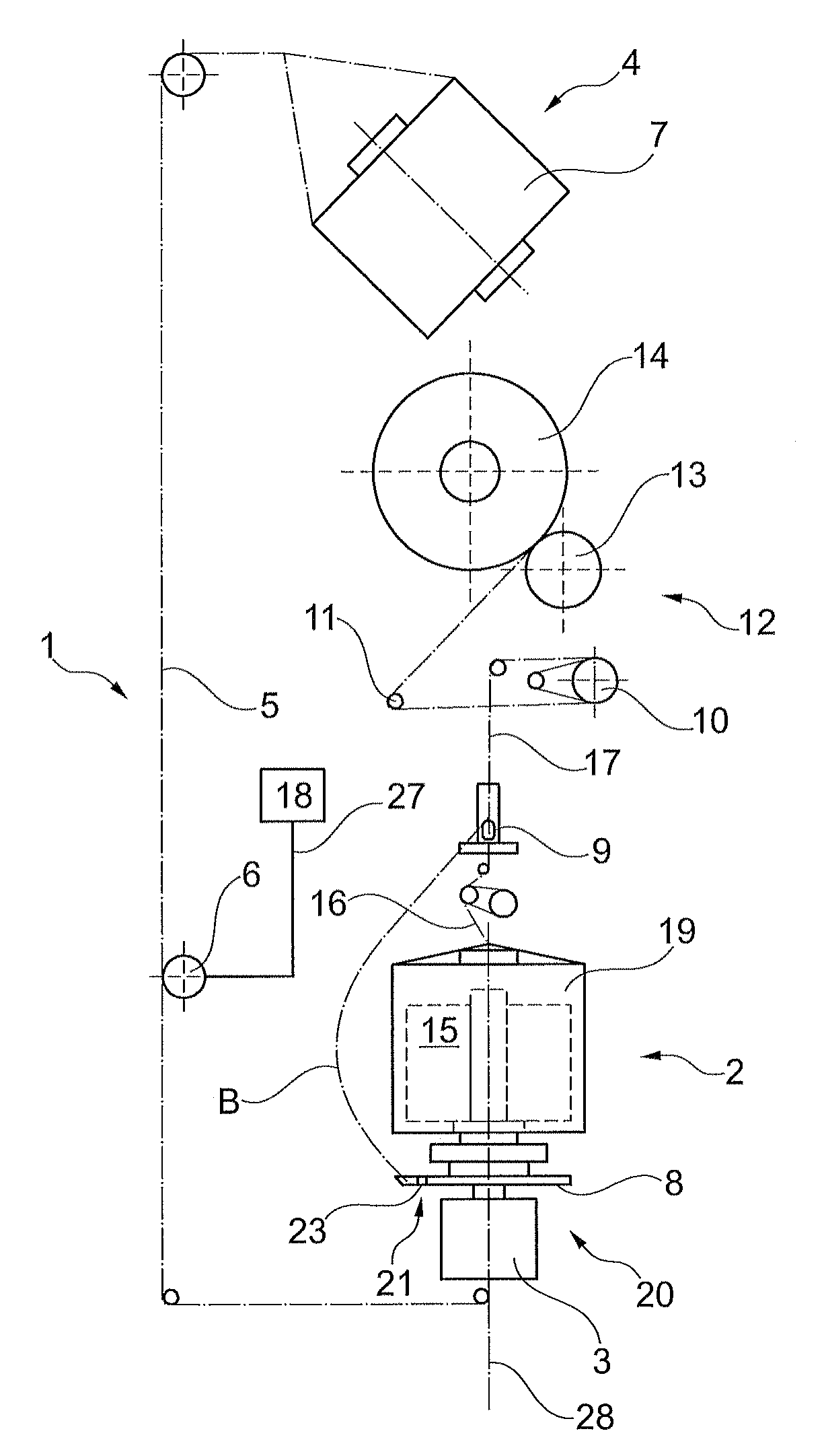
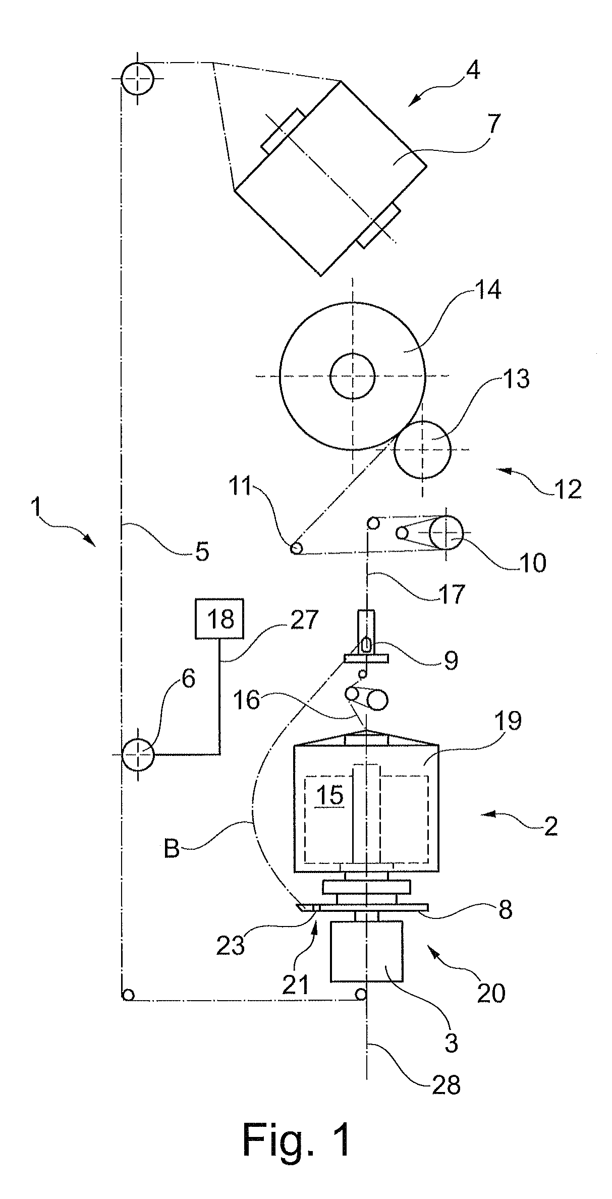
[0056]FIG. 1 shows schematically in side view a workstation of a two-for-one twisting or cabling machine which is denoted overall by the reference numeral 1.

[0057]With reference to the shown workstation 1 the method according to the invention is also explained in the following.

[0058]The workstation 1 of the two-for-one twisting or cabling machine comprises, as usual, a creel 4 positioned above or behind the workstation 1, which is used for mounting at least one first feed package 7 from which a so-called outer yarn 5 is drawn.

[0059]The workstation 1 also has a spindle 2, which is designed in the present example embodiment as a so-called cabling spindle.

[0060]The spindle 2 comprises a spindle pot 19 in which a second feed package 15 is mounted from which a so-called inner yarn 16 is drawn off over head which is supplied to a balloon eyelet arranged above the spindle 2 or a so-called balancing system 9.

[0061]The spindle pot 19 is mounted on the rotatable yarn deflection device 20 whic...


PUM

PropertyMeasurementUnit
tensionaaaaaaaaaa
yarn tensionaaaaaaaaaa
sizeaaaaaaaaaa

Abstract

A method for operating a spindle (2) of a two-for-one twisting or cabling machine, in which an outer yarn (5) is drawn off a first feed package (7) and the spindle (2) rotates in a yarn balloon (B), wherein the spindle (2) comprises a device (6) for influencing the balloon yarn tension of an outer yarn (5), which is connected to a control circuit (18), and has a spindle pot (19) for receiving a second feed package (15), a yarn deflection device (20), a balancing system (9) for forming a twisting or cabling point as well as a spooling and winding device (12). The drive of the yarn balloon (B) is performed via a fixed throw-off point (21) on the yarn deflection device (20).

Description

CROSS-REFERENCE TO RELATED APPLICATIONS[0001]This application claims priority from German National Patent Application No. DE 102015005447.3, filed Apr. 28, 2015, entitled “Verfahren zum Betrelben einer Spindel einer Doppeldrahtzwirn oder Kabliermaschine sowie zugehörige Doppeldrahtzwirn oder Kabliermaschine”, the entire contents of which are incorporated herein by reference.FIELD OF THE INVENTION[0002]The present invention relates to a method for operating a spindle of a two-for-one twisting or cabling machine and a two-for-one twisting or cabling machine for carrying out such method.BACKGROUND OF THE INVENTION[0003]The spindle of a two-for-one twisting or cabling machine is known to be used for the production of twisting, winding yarns or the like from at least two yarns drawn off bobbins, which are generally referred to as an inner yarn or outer yarn.[0004]The bobbin for the inner yarn is often positioned in a so-called spindle pot, which is supported in the region of the axis of ...

Claims


Application Information

Patent Timeline
Patent Type & Authority Patents(United States)
IPC IPC(8): D01H1/10D02G3/28D01H7/86D01H15/00D01H15/007D01H13/10
CPCD01H15/007D01H1/10D01H7/86D02G3/285D01H13/106D01H15/00D02G3/28D01H7/866D01H7/04D01H7/18D01H13/10D01H7/868D01H13/04
Inventor HIEPP, MAGNUSPEDE-VOGLER, WALTERTHALER, ALEXANDER
Owner SAURER TECH GMBH & CO KG
Why Eureka
Try Eureka