Optimizing acoustic efficiency of a sonic filter or separator

a sonic filter or separator technology, applied in the direction of mechanical vibration separation, liquid/fluent solid measurement, instruments, etc., can solve the problems of back reflection and reduce the operating efficiency, and achieve the effect of improving the operating efficiency

Active Publication Date: 2014-10-09
CIDRA CORP SERVICES
View PDF6 Cites 10 Cited by
  • Summary
  • Abstract
  • Description
  • Claims
  • Application Information

AI Technical Summary

Benefits of technology

[0009]The present invention provides for a proper selection of the thickness and/or material to ensure that a ½ wavelength of a desired frequency exi

Problems solved by technology

However, one problem with this type of configuration is that the interface between the fluid and the container wall causes back reflections (toward the transducer) due to the mismatch i

Method used


Image

  • Optimizing acoustic efficiency of a sonic filter or separator
  • Optimizing acoustic efficiency of a sonic filter or separator

Examples


Embodiment Construction

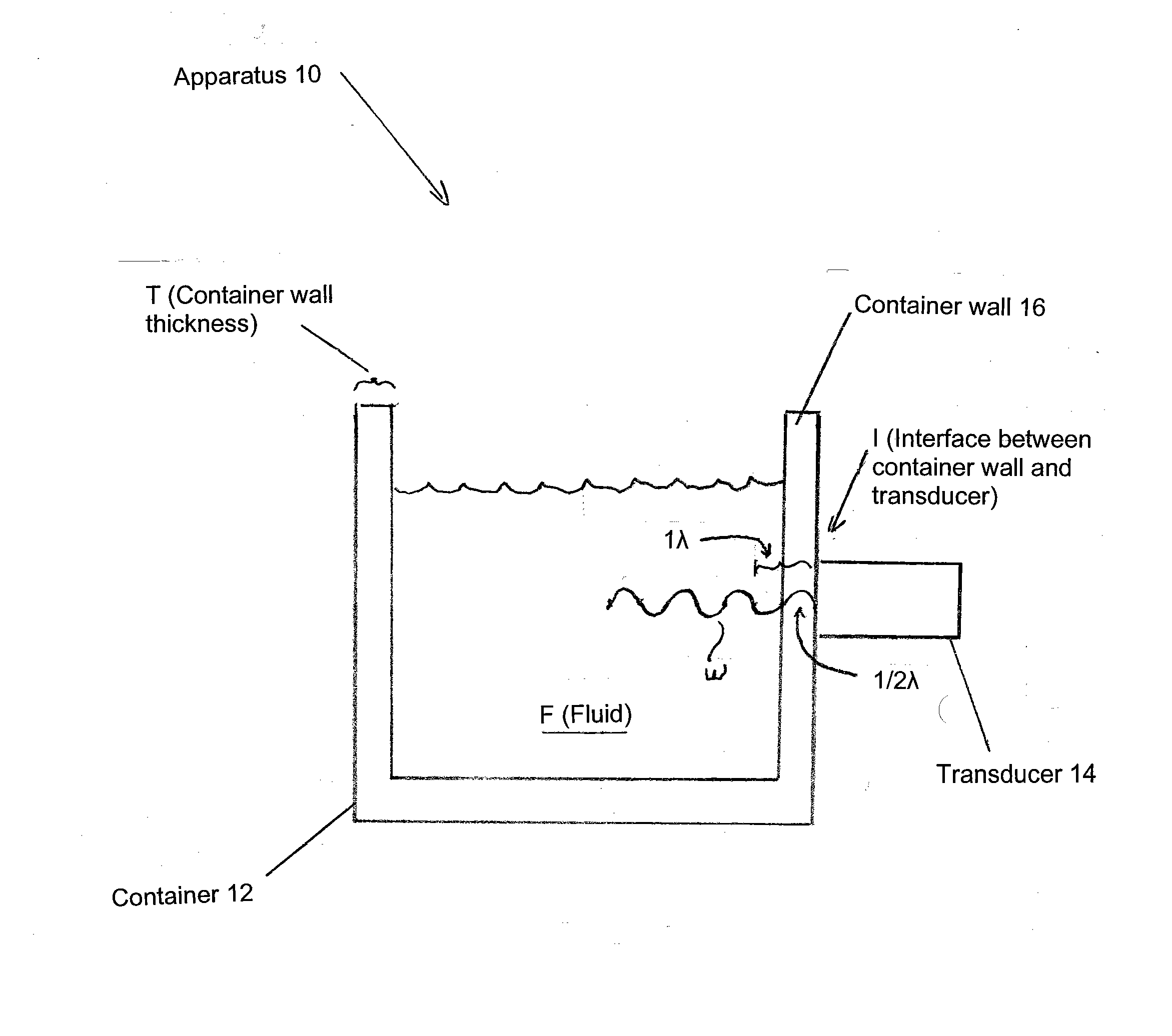
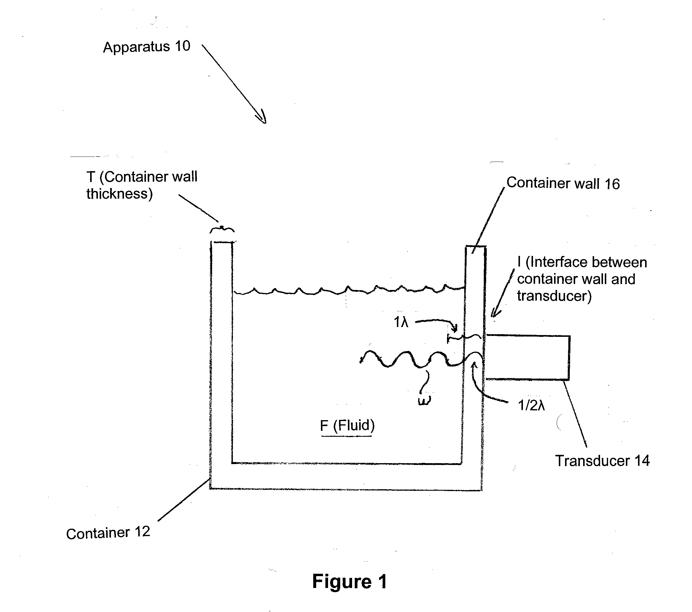
[0019]By way of example, FIG. 1 shows the present invention in the form of apparatus generally indicated as 10 featuring a container 12 in combination with a transducer 14. The container 12 has a container wall 16 characterized by at least one parameter, including being made of a selected type of material or having a selected thickness T. The container 12 is configured to hold a fluid F therein. The transducer 14 is configured on the outside of the container wall 16, and is also configured to provide a standing wave W into the fluid F.

[0020]The at least one parameter of the container wall 16 is selected to ensure about a ½ wavelength (½λ) of a desired frequency exists within the container wall 16, so as to substantially reduce back reflections toward the transducer 14 due to any mismatch in acoustic impedance at the interface I between the container wall 16 and the fluid F, and so as to substantially maximize the amount of energy delivered to the fluid F, thus improving the operatin...


PUM


Abstract

Apparatus features a container and a transducer. The container is made of a selected material and has a container wall with a selected thickness, and configured to hold a fluid therein. The transducer is configured on the outside of the container wall, and is also configured to provide a standing wave into the fluid. The selected thickness and material of the container wall is chosen to ensure about a ½ wavelength of a desired frequency exists within the container wall, so as to substantially reduce back reflections toward the transducer due to any mismatch in acoustic impedance at the interface between the container wall and the fluid, and so as to substantially maximize the amount of energy delivered to the fluid, thus improving the operating efficiency of the apparatus.

Description

CROSS-REFERENCE TO RELATED APPLICATIONS[0001]This application claims benefit to provisional patent application Ser. No. 61 / 439,540 (CCS-0041), filed 4 Feb. 2011, which is incorporated by reference in their entirety.BACKGROUND OF THE INVENTION[0002]1. Field of Invention[0003]The present invention relates to a technique for providing a standing wave into fluid in a container.[0004]2. Description of Related Art[0005]Sonic filters and separators based upon standing wave agglomeration are known and have been demonstrated. The efficiency of such filters is determined by the amount of electrical energy required to obtain a specified level of separation.[0006]Typically, a standing wave may be set up in a fluid by acoustically driving the fluid by situating an appropriate transducer to the outside of the container containing the fluid. However, one problem with this type of configuration is that the interface between the fluid and the container wall causes back reflections (toward the transd...

Claims


Application Information

Patent Timeline
IPC IPC(8): B01J19/10
CPCB01J2219/0877B01J19/10G01F23/2961G01F23/2967B03D1/028
Inventor FERNALD, MARK R.BAILEY, TIMOTHY J.
Owner CIDRA CORP SERVICES
Why Eureka
Try Eureka