Power decoupling controller and method for power conversion system

a power conversion and controller technology, applied in the direction of dc-ac conversion without reversal, process and machine control, instruments, etc., can solve the problem of difficult control of active and reactive power separately

Active Publication Date: 2014-10-16
GENERAL ELECTRIC CO
View PDF6 Cites 38 Cited by
  • Summary
  • Abstract
  • Description
  • Claims
  • Application Information

AI Technical Summary

Benefits of technology

[0007]In accordance with another embodiment disclosed herein, a method of operating a power conversion system is provided. The method includes generating a phase angle command signal based on an active power command signal and an active power feedback signal; generating a voltage magnitude command signal based on a reactive power command signal and a reactive power feedback signal; generating a phase angle compensation signal based on a reactive power error signal, to compensate the phase angle command signal; generating a voltage magnitude compensation signal based on an active power error signal, to compensate the voltage magnitude command signal; and generating control signals for a power converter of the power conversion system for causing an AC voltage output from the power converter to decouple interaction between an active power loop and a reactive power loop based on the compensated phase angle command signal and the compensated voltage magnitude command signal.

Problems solved by technology

The interaction between active and reactive power makes it difficult to control active and reactive power separately.

Method used


Image

  • Power decoupling controller and method for power conversion system
  • Power decoupling controller and method for power conversion system
  • Power decoupling controller and method for power conversion system

Examples


Embodiment Construction

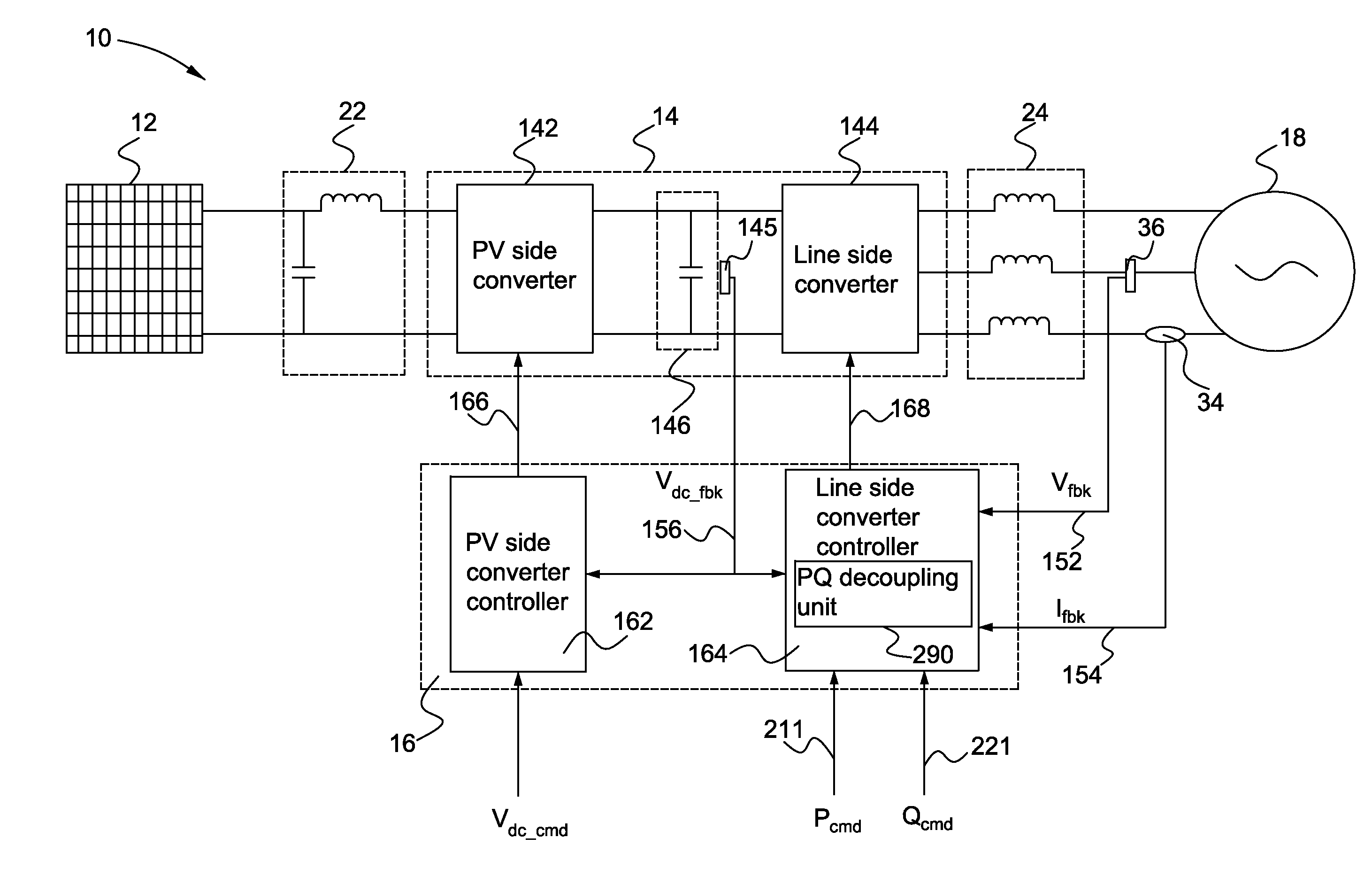
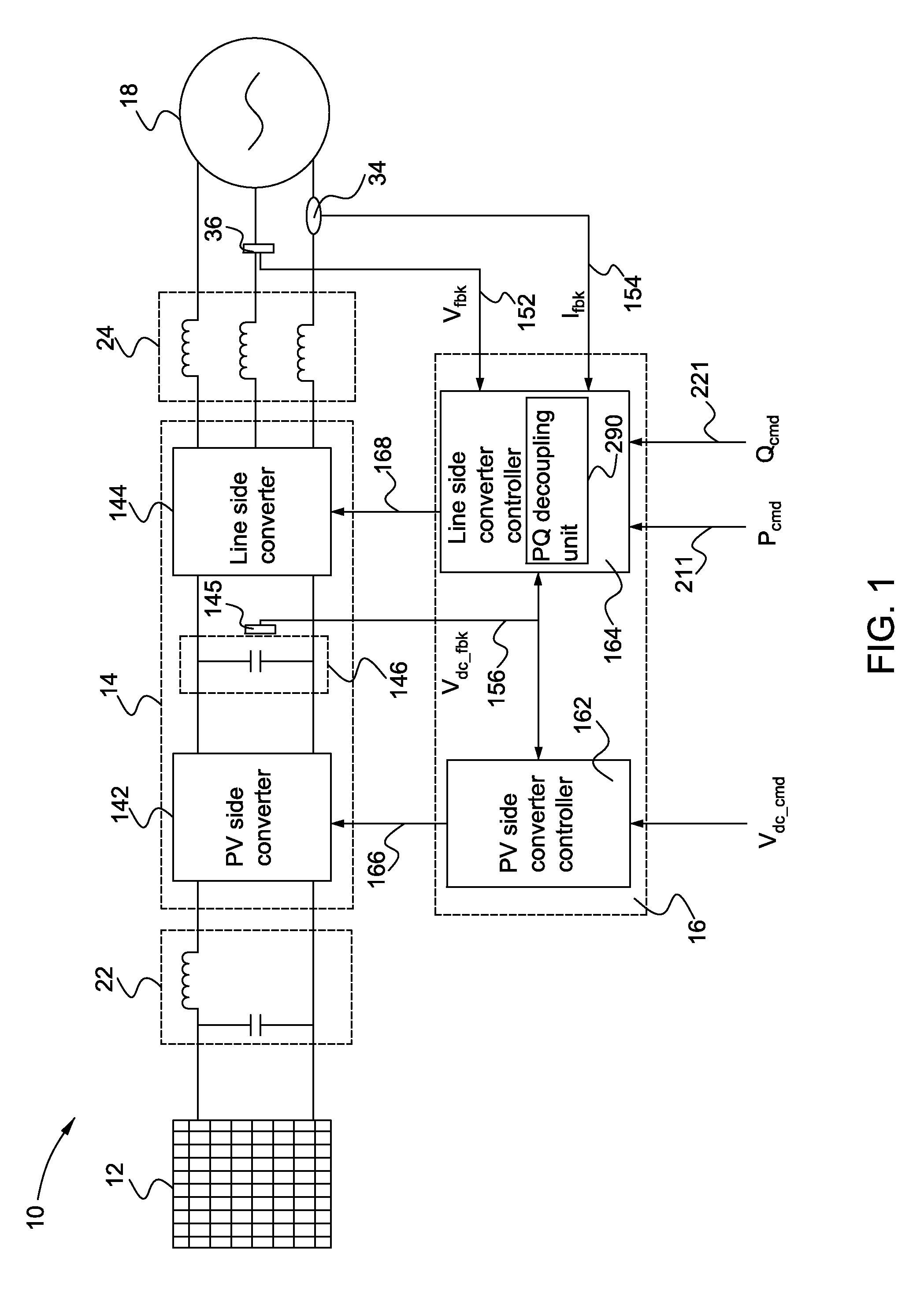
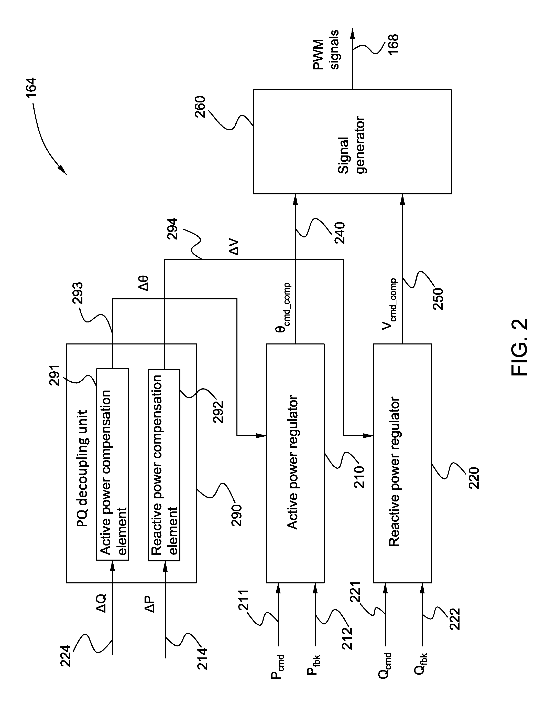
[0019]Embodiments disclosed herein relate generally to a power conversion system having compensation functions to decouple / eliminate the interaction between the active power loop and the reactive power loop of the power conversion system. The power conversion system includes a DC bus for receiving DC power, a power converter for converting the DC power to AC power, and a controller. The controller includes an active power regulator for generating a phase angle command signal, a reactive power regulator for generating a voltage magnitude command, and an active power (P) and reactive power (Q) decoupling unit for decoupling interaction between the active and reactive power regulators. The PQ decoupling unit includes an active power compensation element and a reactive power compensation element. The active power compensation element is used for generating a phase angle compensation signal based on a reactive power error signal, to compensate the phase angle command signal. The reactive...


PUM


Abstract

A power conversion system is disclosed including a DC bus for receiving DC power, a power converter for converting the DC power to AC power, and a controller. The controller includes an active power regulator for generating a phase angle command signal, a reactive power regulator for generating a voltage magnitude command, and an active power (P) and reactive power (Q) decoupling unit for decoupling interaction between the active and reactive power regulators. The PQ decoupling unit includes an active power compensation element and a reactive power compensation element. The active power compensation element is used for generating a phase angle compensation signal based on a reactive power error signal, to compensate the phase angle command signal. The reactive power compensation element is used for generating a voltage magnitude compensation signal based on an active power error signal, to compensate the voltage magnitude command signal.

Description

BACKGROUND[0001]Embodiments of the disclosure relate generally to power conversion systems and methods for converting and providing electrical power to feed an electrical system.[0002]Renewable power, such as solar power generated by solar power generation systems, is becoming a larger source of energy throughout the world. A typical solar power generation system includes one or more photovoltaic arrays (PV arrays) having multiple interconnected solar cells. The solar cells of the PV arrays convert solar energy into DC power. In order to interface the output of the PV arrays to a power grid, a solar power converter is typically used to change the DC power from the PV arrays into AC power to feed a power grid.[0003]Various solar power converter configurations exist for converting the DC power output from PV arrays into AC power. One implementation of a solar power converter has two stages including a DC-DC converter stage and a DC-AC converter stage. The DC-DC converter controls the ...

Claims


Application Information

Patent Timeline
Patent Type & Authority Applications(United States)
IPC IPC(8): H02M7/537
CPCH02M7/537H02M7/48H02J3/48H02J3/50H02J2300/24H02J3/381H02J3/46Y02E10/56
Inventor WU, XINHUILIU, JIAOHOU, DANWU, XUEQINTAN, ZHUOHUI
Owner GENERAL ELECTRIC CO
Why Eureka
Try Eureka