Variable diameter pipe clamp apparatus and torque module therefor

a technology of torque module and pipe clamp, which is applied in the direction of drilling casing, drilling pipe, and accessories of wellbore/well, etc., can solve the problems of significant cost to drillers, waste of time changing, and delay in oil extraction

Inactive Publication Date: 2014-10-23
BERTELSEN JEFFREY LEE
View PDF4 Cites 7 Cited by
  • Summary
  • Abstract
  • Description
  • Claims
  • Application Information

AI Technical Summary

Problems solved by technology

The time it takes, “connection time”, delays extraction of oil and is a significant cost to drillers.
Often this can mean up to 5 to 7 different diameter pipe handling devices such as slips, drill collars, tongs, as well as wasted time changing between these devices or changing the devices to different pipe sizes.
This design applies all of the force in a small area about 1″ by 5″ on either side of the pipe; if the applied force is too high in this small area it will cause the pipe to become deformed, or “egg-shaped”, damaging the pipe.
This becomes an issue, as pressure is not distributed evenly on the clamps during the torque operations.
Further, as the clamps provide only two points of pressure on the pipe, and not a uniform pressure, there is the possibility of slippage and / or deformation of the pipe under intense forces (typically in upwards of 100,000 ft-lbs) applied by the clamps to hold the pipe in place.
This conventional cylinder design in the torque module is also limited to rotate or work one sided, i.e. it cannot go both clockwise (CW) and counter-clockwise (CCW) from a neutral position, only CW or CCW only-one direction.
This limitation will cause what is referred to as the “breakout operation” (i.e., disconnect) to be a two-step process instead of a single step.
Moreover, the 37 degree limitation can also cause the torque process to require multiple movement steps, as a rotation may require greater than a 37 degree movement on the pipe with the clamp.

Method used


Image

  • Variable diameter pipe clamp apparatus and torque module therefor
  • Variable diameter pipe clamp apparatus and torque module therefor
  • Variable diameter pipe clamp apparatus and torque module therefor

Examples


Embodiment Construction

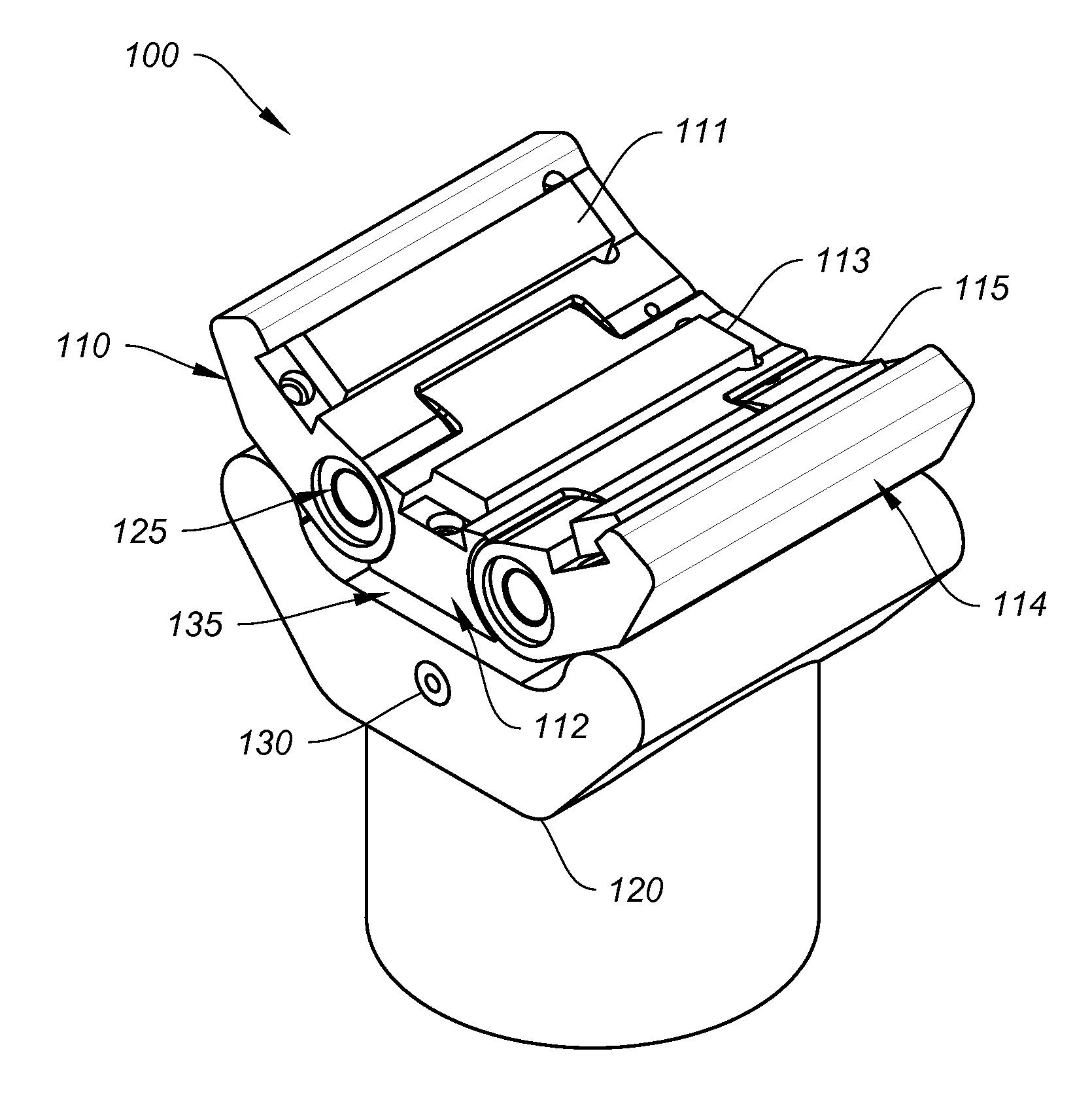
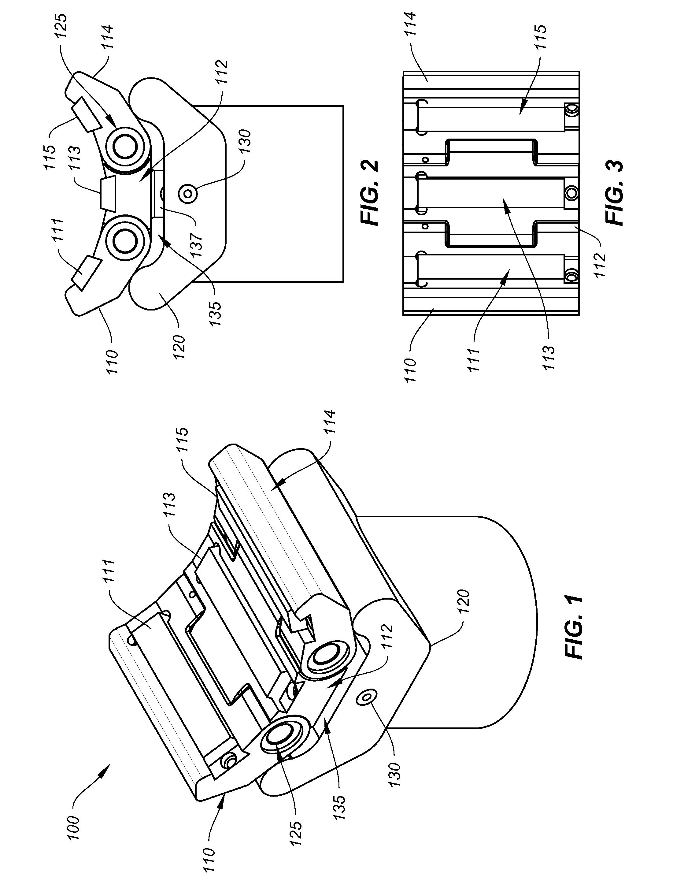
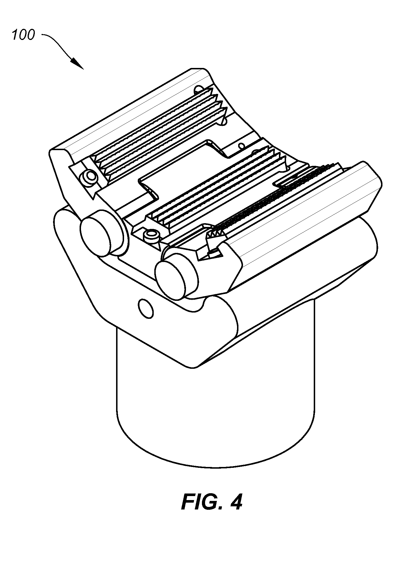
[0026]As to be described hereafter, an example embodiment is directed to a pipe clamp apparatus adapted to automatically adjust to pipes of variable diameters, and a torque module for the pipe clamp apparatus for applying torque thereto.

[0027]As to be shown hereafter, the pipe clamp apparatus may be used to torque pipe, hold pipe, move pipe, and / or handle pipe. The pipe clamp apparatus is configured so as to automatically adjust to any desired range of pipe diameters, unlike existing pipe clamps which must utilize inserts and / or change out the dies to account for changing pipe diameters. In one example, the pipe clamp apparatus may automatically adjust to pipe having a diameter in a range of about 4″ to 10″ in diameter pipe, to be torqued up to about 150,000 ft-lb′ via the example torque module to be described hereafter. Accordingly, the example clamp apparatus offers a variable radius clamp design to enable an operator to change pipe diameters without changing clamp dies, while sti...


PUM


Abstract

A combination for making up and breaking out pipe at an oil rig site includes a torque module and at least one pipe clamp apparatus. The torque module includes a pair of hydraulic motors, a torque transmission driven by the motors, a herringbone gear segment driven by the transmission to rotate the torque module, and a pair of clamp cylinders actuated by the transmission. The at least one pipe clamp apparatus is actuated by at least one of the clamp cylinders to apply a uniform gripping load around a pipe that is pipe diameter independent.

Description

CROSS-REFERENCE TO RELATED APPLICATION[0001]The present application claims the benefit under 35 U.S.C. §119(e) of U.S. Provisional Patent Application No. 61 / 639,956 to the inventor, filed Apr. 29, 2012, the entire contents of which is hereby incorporated by reference herein.BACKGROUND[0002]1. Field[0003]Example embodiments generally relate to a pipe clamp apparatus adapted to automatically adjust to pipes of variable diameters, and a torque module for the pipe clamp apparatus for applying torque thereto.[0004]2. Related Art[0005]Conventionally at an oil rig site, various diameters of piping are used in order to extract fossil fuels deep beneath the earth's crust. Various sections of different diameters are connected via drill collars on the inward direction into the well, as well as on the extraction direction. The time it takes, “connection time”, delays extraction of oil and is a significant cost to drillers.[0006]Accordingly, a site will typically have a number of different sized...

Claims


Application Information

Patent Timeline
Patent Type & Authority Applications(United States)
IPC IPC(8): E21B19/16
CPCE21B19/164E21B19/161E21B4/006
Inventor BERTELSEN, JEFFREY LEE
Owner BERTELSEN JEFFREY LEE
Why Eureka
Try Eureka