Capillary wall coupled whispering gallery mode microresonator

a micro-resonator and capillary wall technology, applied in the field of micro-resonator structures, can solve the problems of difficult coupling of light into the microsphere to excite whispering gallery waves in a robust and cost-effective package, and achieve the effect of reducing the thickness of the sidewall

Active Publication Date: 2014-10-23
UNIVERSITY OF MISSOURI
View PDF4 Cites 5 Cited by
  • Summary
  • Abstract
  • Description
  • Claims
  • Application Information

AI Technical Summary

Benefits of technology

[0008]A third embodiment of the current invention provides a method of forming a microresonator structure. The method comprises the steps of: coupling a first end of a hollow cylindrical capillary to a first optical fiber, forming an inwardly tapering inner surface of a sidewall of the capillary, placing a microsphere in the capillary so that the microsphere contacts the inner surface, sealing a second end of the capillary with a second optical fiber, and reducing the thickness of the sidewall of the capillary.

Problems solved by technology

However, coupling the light into the microsphere to excite whispering gallery waves in a robust and cost-effective package can be difficult.

Method used


Image

  • Capillary wall coupled whispering gallery mode microresonator
  • Capillary wall coupled whispering gallery mode microresonator
  • Capillary wall coupled whispering gallery mode microresonator

Examples


Embodiment Construction

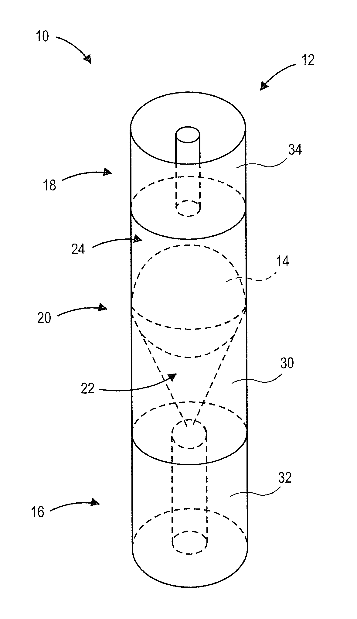
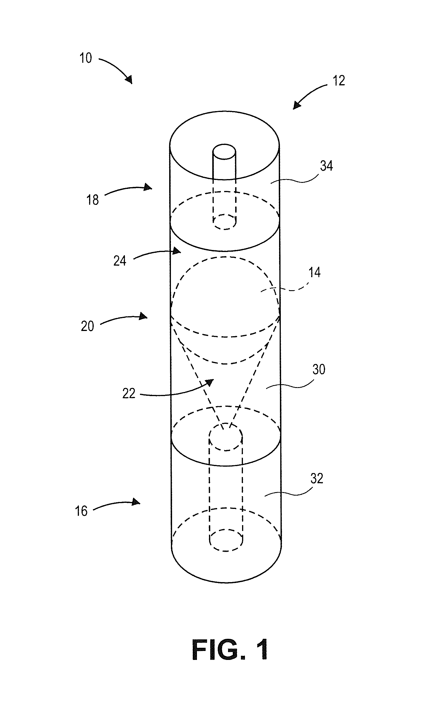
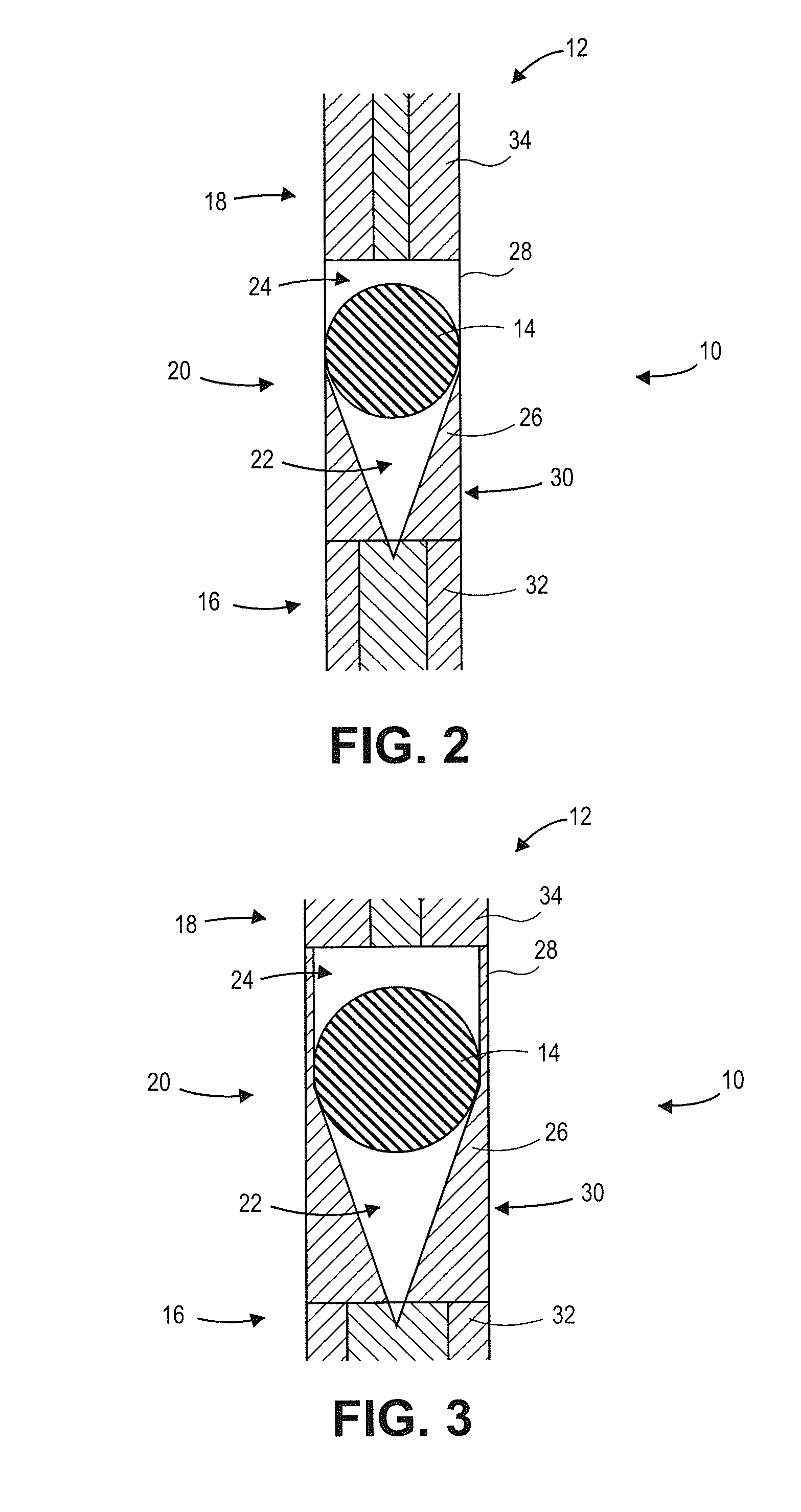
[0018]The following detailed description of the invention references the accompanying drawings that illustrate specific embodiments in which the invention can be practiced. The embodiments are intended to describe aspects of the invention in sufficient detail to enable those skilled in the art to practice the invention. Other embodiments can be utilized and changes can be made without departing from the scope of the current invention. The following detailed description is, therefore, not to be taken in a limiting sense. The scope of the current invention is defined only by the appended claims, along with the full scope of equivalents to which such claims are entitled.

[0019]In this description, references to “one embodiment”, “an embodiment”, or “embodiments” mean that the feature or features being referred to are included in at least one embodiment of the technology. Separate references to “one embodiment”, “an embodiment”, or “embodiments” in this description do not necessarily ref...


PUM

PropertyMeasurementUnit
diameteraaaaaaaaaa
outer diameteraaaaaaaaaa

Abstract

A microresonator structure comprises a waveguide and a microsphere. The waveguide is of elongated cylindrical shape and includes a first section of optical transmission material and a cavity section axially aligned with the first section. The cavity section includes a first cavity and a second cavity. The first cavity is adjacent to the first section and includes a first sidewall of optical transmission material with an inner surface that tapers inward to an apex positioned adjacent to the first section. The second cavity is positioned adjacent to the first cavity of hollow cylindrical shape and includes a circumferential second sidewall of optical transmission material that abuts the first sidewall. The microsphere has a spherical outer surface and is positioned within the cavity section such that the outer surface contacts a portion of the first sidewall and a portion of the second sidewall.

Description

BACKGROUND OF THE INVENTION[0001]1. Field of the Invention[0002]Embodiments of the current invention relate to microresonator structures.[0003]2. Description of the Related Art[0004]Microspheres are small spherical objects constructed from optical transmission material. Typically, microspheres have a diameter on the order of 10-100 micrometers. Within a concave or arcuate shaped inner surface, such as the interior of a microsphere, waves traveling along the surface decay much less than waves traveling in other directions and are known as whispering gallery waves. When light is coupled into a microsphere at an appropriate incidence angle, the light becomes whispering gallery waves that resonate within the microsphere. Microspheres that are excited with whispering gallery resonant waves may be utilized in sensing and lasing applications. However, coupling the light into the microsphere to excite whispering gallery waves in a robust and cost-effective package can be difficult.SUMMARY O...

Claims


Application Information

Patent Timeline
Patent Type & Authority Applications(United States)
IPC IPC(8): G02B6/30
CPCG02B6/305G02B6/29341Y10T29/49815Y10T29/49826
Inventor XIAO, HAIWANG, HANZHENG
Owner UNIVERSITY OF MISSOURI
Why Eureka
Try Eureka