Light detection system and method

a detection system and light detection technology, applied in the field of illumination light detection systems, can solve the problems of inability to detect embedded data present at single positions, use of advanced and therefore expensive cameras capable of providing a high acquisition rate, and the general duration between subsequent image acquisitions must be equal or shorter than the duration

Active Publication Date: 2014-10-23
KONINKLIJKE PHILIPS ELECTRONICS NV
View PDF3 Cites 75 Cited by
  • Summary
  • Abstract
  • Description
  • Claims
  • Application Information

AI Technical Summary

Benefits of technology

[0008]It is an object of the present invention to overcome the above mentioned problems, and to provide a light detection system and a method capable of detecting 2D CL embedded into a light output of light sources in a manner that allows identification of the embedded codes of the different light sources being present in a 2D scene. It is a further object of the invention to provide a detection system and method suitable for detecting high frequency CL while using less expensive cameras as those used in previous techniques.

Problems solved by technology

This has a drawback that only embedded data present at single positions can be detected.
However, a drawback of the previous techniques employing camera sensors is that the time between subsequent image acquisitions must generally be equal to, or shorter than, the duration of a single bit within the embedded code.
This requires the use of advanced and therefore expensive cameras capable of providing a high acquisition rate.
Conventional low-cost camera sensors typically have too low of an acquisition rate to be useful for detecting embedded data being invisible to the human eye, i.e. high frequency CL.

Method used


Image

  • Light detection system and method
  • Light detection system and method
  • Light detection system and method

Examples


Embodiment Construction

[0042]The present invention will now be described more fully hereinafter with reference to the accompanying drawings. The below embodiments are provided by way of example so that this disclosure will be thorough and complete, and will fully convey the scope of the invention to those skilled in the art. Like numbers refer to like elements throughout.

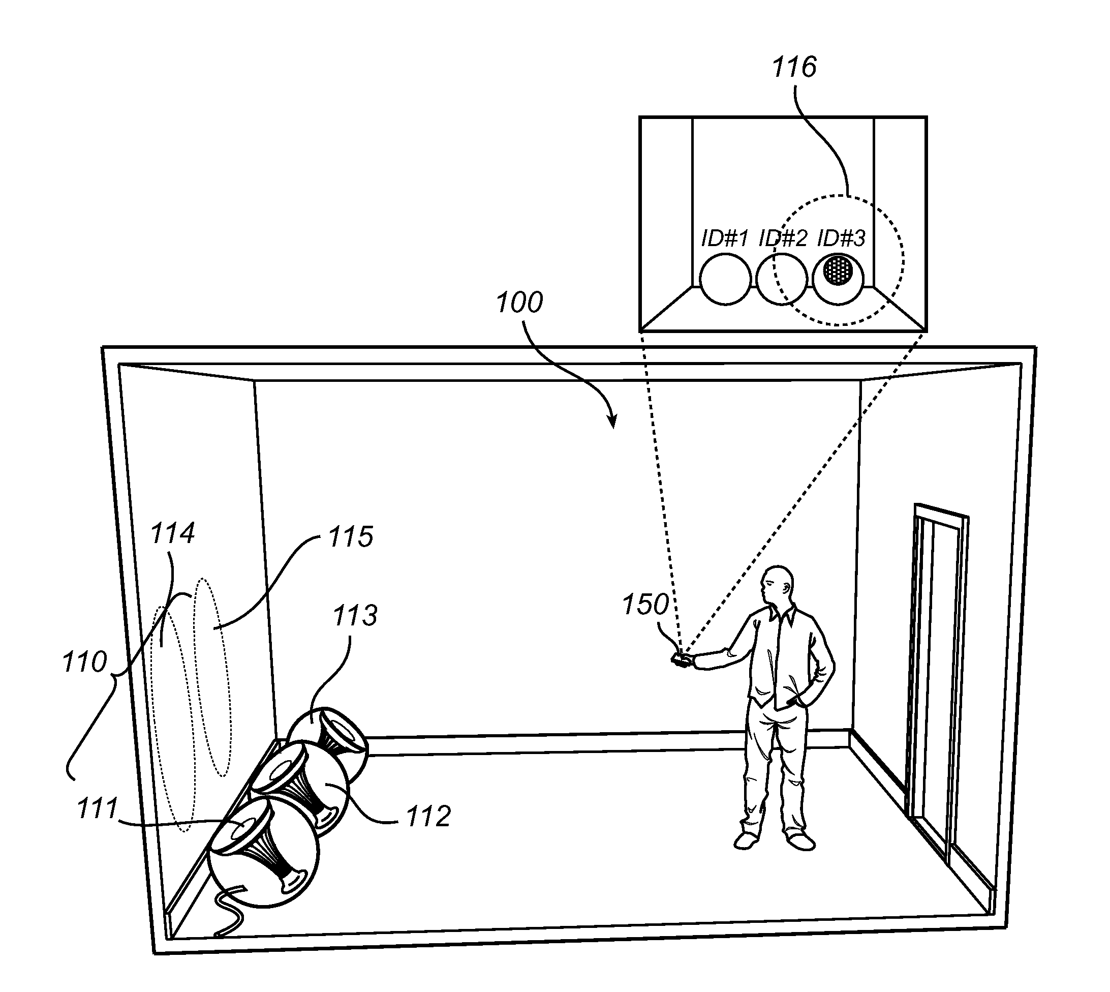
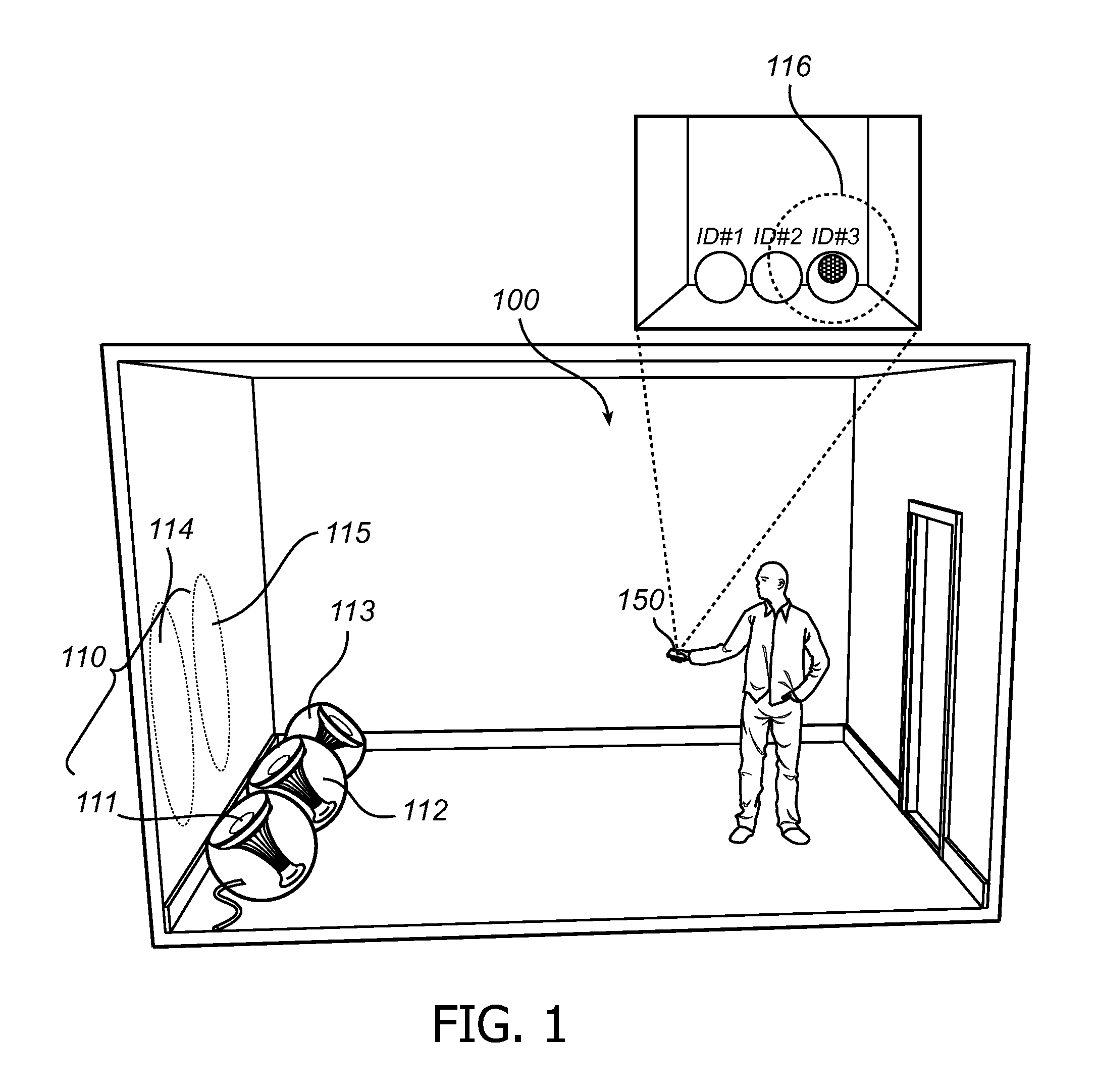
[0043]FIG. 1 illustrates a structure 100, here being a room, in which an illumination system 110 is installed. The illumination system 110 comprises three light sources 111, 112, and 113, and one or more control units for controlling the light sources 111, 112, 113. The illumination system here comprises a remote control 150 for allowing a user to control the light sources. The light sources may comprise any suitable source of light like high / low pressure gas discharge sources, laser diodes, inorganic / organic light emitting diodes, incandescent sources, or halogen sources. During operation the individually provided light output I111, I112...


PUM


Abstract

There is provided a light detection system which is capable of determining in light embedded codes by detecting light in a scene which is illuminated by an illumination system (110) comprising one or more light sources (111,112,113) each providing a light contribution (I111, I112, I113) comprising an embedded code (ID#1, ID#2, ID#3) emitted as a temporal sequence of modulations in a characteristics of the light emitted. The light detection system comprises light detection means (220), which are arranged for acquiring at least one image of the scene, where the image is acquired a plurality of temporal shifted line instances. Each line of the acquired image comprises an instance of the temporal sequence of modulations of the first embedded code. The light detection system further comprises means (230) for determining embedded codes from the spatial pattern of modulations.

Description

FIELD OF THE INVENTION[0001]The present invention relates generally to the field of illumination light detection systems, and more particularly to a system and method for detecting data embedded into the light output of such illumination systems.BACKGROUND OF THE INVENTION[0002]In recent years, highly advanced illumination systems are being developed to allow a user to obtain a desired ambiance for a particular room or space. In these illumination systems so called scene setting is employed, where one or more sets of light sources are controlled simultaneously, contrary to traditional control of individual light sources with respect to e.g. switching on / off, dimming, and color setting. For these scene setting applications, intuitive user interaction is an important success factor. Providing a user with information related to the light sources, like localized identification of the individual light sources, their capacities, and their current setting, is key for enabling an intuitive ...

Claims


Application Information

Patent Timeline
Patent Type & Authority Applications(United States)
IPC IPC(8): H04B10/116H04N5/225H04B10/548H05B37/02H04B10/69H04B10/54
CPCH04B10/116H04B10/69H04N5/225H04B10/548H05B37/02H04B10/54H05B47/19H05B47/155H05B47/10H04N23/00H04N25/531H04N23/56H04N23/70
Inventor DE BRUIJN, FRITSVLUTTERS, RUUDFERI, LORENZOSCHENK, TIMRIETMAN, RONALD
Owner KONINKLIJKE PHILIPS ELECTRONICS NV
Why Eureka
Try Eureka